pfSense router-on-a-stick VLAN configuration with a Mikrotik SG260GS
Last revised 20 March 2016.
Introduction
My recent pfSense guide makes extensive use of VLANs to provide enough network segments to facilitate the segregation of devices into the following categories
| Description | VLAN ID | Subnet |
|---|---|---|
| Management Interface | 10 | 192.168.10.0/24 |
| VPN LAN | 20 | 192.168.20.0/24 |
| ClearNet LAN | 30 | 192.168.30.0/24 |
| Guest network | 40 | 192.168.40.0/24 |
| Security cameras | 50 | 192.168.50.0/24 |
| DMZ | 60 | 192.168.60.0/24 |
| Game consoles | 70 | 192.168.70.0/24 |
| VoIP phones | 80 | 192.168.80.0/24 |
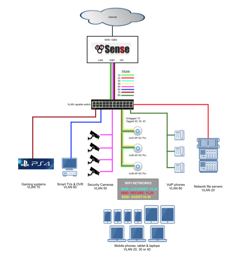
Without VLANs it would be tough to provide enough network interface connections to enable me to apply strict firewall rules and traffic prioritisation to support my needs. For example, the video surveillance system is confined to a single VLAN and has very limited abilities to communicate with devices in other subnets and the internet and my gaming consoles have prioritisation to ensure smooth and problem free network play. These Virtual LAN (VLAN) segments are connected back to pfSense in a ‘router-on-a-stick’ configuration. Its called a ‘router-on-a-stick’ because of the single trunk cable connecting the 802.1Q capable switch to our pfSense router. This enables our switch to handle local subnet traffic switching whilst retaining pfSense to firewall inter-subnet traffic. Some of my fileservers and devices generate a substantial amount of traffic and not having to push all this traffic through pfSense allows it to better handle the load it does need to process.
Here’s a diagram to help illustrate my configuration.
Introducing the Mikrotik RB260GS
There’s a large range of managed switches capable of handling 802.1Q VLAN tags but I wanted to provide a guide based on a cost effective model. I chose the Mikrotik RB260GS which is available delivered for less than $40. The switch is equipped with 5 RJ45 gigabit ports plus sports a single SFP cage. Models are available with more than 5 ports and its worth considering your future network needs before purchasing to avoid running out of ports.
Configuring the switch
Your own network needs will differ from mine but I’m going to setup the RB260GS ports as follows, hopefully it should be easy enough for you to duplicate or adjust as per your specific needs.
| Port | Description | VLANs |
|---|---|---|
| 1 | Trunk to pfSense router | 1, 10, 20, 30, 40 |
| 2 | Access port VL20_VPN LAN subnet | 20 |
| 3 | Access port VL30_CLRNET LAN subnet | 30 |
| 4 | Hybrid port to Ubiquiti Unifi wifi AP | 10 (untagged), 20, 30, 40 |
| 5 | Management port | None |
| SFP | Disabled | None |
Port 1, Trunk
This is the port that carries all of the traffic between the switch and its individual ports and our pfSense router. In this example we will configure this port to carry the full suite of VLANs.
Port 2, Access port for VL20_VPN
Access ports can only carry traffic for a single VLAN. This port will be configured to physical accept a connection from a device and append the VLAN tag ‘20’ ensuring our traffic is routed on the VL20_VPN interface.
Port 3, Access port for VL30_CLRNET
Another access port, this time configured to append VLAN tag ‘30’ to route traffic on to our Clearnet interface.
Port 4, Hybrid connection for Ubiquiti Unifi wireless access point
I use a number of Ubiquiti wifi access points around my home and office to ensure reliable connections for a number of mobile devices. I’ll cover the configuration of the Unifi hardware in a separate guide.
The Unifi hardware requires a untagged management port and a further three VLANs all of which can be mapped to individual wireless SSID’s. In this case we will configure our trunk port to carry untagged 10 & tagged 20, 30 & 40 representing Management, VPN_LAN, Clearnet_LAN and Guest networks.
Port 5, Management port
I’ll leave port 5 as a management port to ensure simple access to the Mikrotik router. We will use this port in the next stage to perform the configuration.
Port 6, SFP.
Disabled.
For anyone stumbling on this and curious what transceivers work, I tested my Intel transceivers and they were identified correctly, my Chelsio transceivers were not however.
Log into the RB260GS
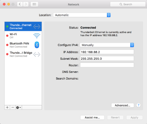
The RB260GS comes preconfigured for access to its management interface at address 192.168.88.1. To log in you will need to configure your PC to an address in the 192.168.88.x subnet, I’ll use 192.168.88.2.
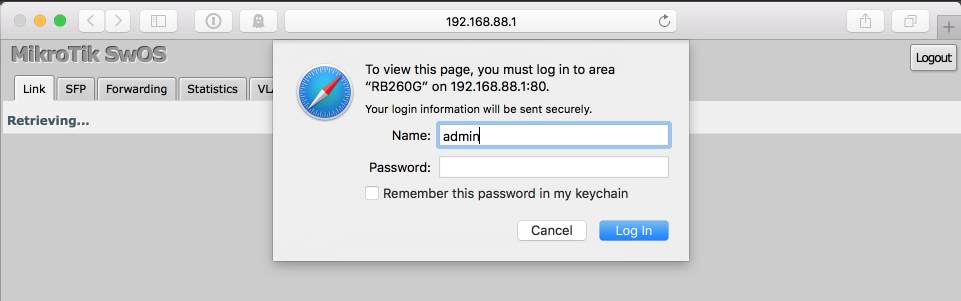
You can now connect a cable form your PC to a RJ45 connection on the RB260GS and proceed to login by accessing 192.168.88.1 from your browser. I’m going to use port 5 as a management interface which will provide a simple means to log in at any time and make adjustments.
Default username = “admin” and the default password is blank.
VLAN configuration
Navigate to the VLAN tab & configure the ports as follows
| Port 1 | Port 2 | Port 3 | Port 4 | Port 5 | SFP | |
|---|---|---|---|---|---|---|
| Ingress | ||||||
| VLAN Mode | enabled | strict | strict | strict | disabled | disabled |
| VLAN Receive | any | only untagged | only untagged | any | any | any |
| Default VLAN ID | 1 | 20 | 30 | 10 | 1 | 1 |
| Force VLAN ID | unticked | unticked | unticked | unticked | unticked | unticked |
| Egress | ||||||
| Vlan Header | add if missing | always strip | always strip | always strip | leave as is | leave as is |
Navigate to the VLANs tab & configure the ports as follows
| VLAN ID | Port 1 | Port 2 | Port 3 | Port 4 | Port 5 | SFP |
|---|---|---|---|---|---|---|
| 1 | Leave as is | Not a member | Not a member | Not a member | Leave as is | Leave as is |
| 10 | Leave as is | Not a member | Not a member | Always strip | Leave as is | Leave as is |
| 20 | Leave as is | Always strip | Not a member | Leave as is | Leave as is | Leave as is |
| 30 | Leave as is | Not a member | Always strip | Leave as is | Leave as is | Leave as is |
| 40 | Leave as is | Not a member | Not a member | Leave as is | Leave as is | Leave as is |
Connect and test
If you connect a cable between port 1 of your Mikrotik switch and the port you configured to act as the parent interface on your pfSense router you should be able to connect a device to port 2 or 3 and obtain a DHCP address from the DHCP server from the appropriate address pools.
Regardless of any configuration gotchas, port 5 should still allow you to log into the Mikrotik router at 192.168.88.1 and to further configuration changes.
Be mindful of trunk bandwidth
Even though you can go wild and create hundreds of VLAN interfaces and load them up with a multitude of devices, its worth keeping in mind that all the traffic between the switch and the router, i.e the stick, has to go across a single 1 gig UTP cable and therefore is capped at 1gbps. It is possible to use a few techniques to increase this bandwidth and provide additional overhead if required.
Firstly and most cheaply, you can bond a number of RJ45 connections together into a Link Aggregation Group (LAGG), however its worth noting that this won’t break down a single clients traffic into multiple parallel streams, traffic is distributed in a round-robin manner across the multiple links so a heavy single threaded connection won’t see any benefit.
Secondly, and my preferred albeit slightly more expensive method, is to migrate the 1gig trunk connection onto a 10gig link. This requires a 10gig network card such as the Intel X520/540 or Chelsio T4/T5 be added to your pfSense router as well as a switch which offers a 10gig uplink. I prefer SFP+ connections over RJ45 due to lower latencies and lower power requirements which reduces electricity consumption and heat which usually requires loud fans to dissipate.