pfSense router-on-a-stick VLAN configuration with a Netgear GS108E
Last revised 28 February 2018.
Due to the uneccessary and additional complication of having to resort to using a specific configuration utility with the GS108Ev2 product featured in this guide, I would advise readers look for the updated v3 product which provides a web-based management interface. </a>
Introduction
My recent pfSense guide makes extensive use of virtual LANs (VLANs) to provide enough network segments to facilitate the segregation of devices into the following categories
| Description | VLAN ID | Subnet |
|---|---|---|
| Management Interface | 10 | 192.168.10.0/24 |
| VPN LAN | 20 | 192.168.20.0/24 |
| ClearNet LAN | 30 | 192.168.30.0/24 |
| Guest network | 40 | 192.168.40.0/24 |
| Security cameras | 50 | 192.168.50.0/24 |
| DMZ | 60 | 192.168.60.0/24 |
| Game consoles | 70 | 192.168.70.0/24 |
| VoIP phones | 80 | 192.168.80.0/24 |
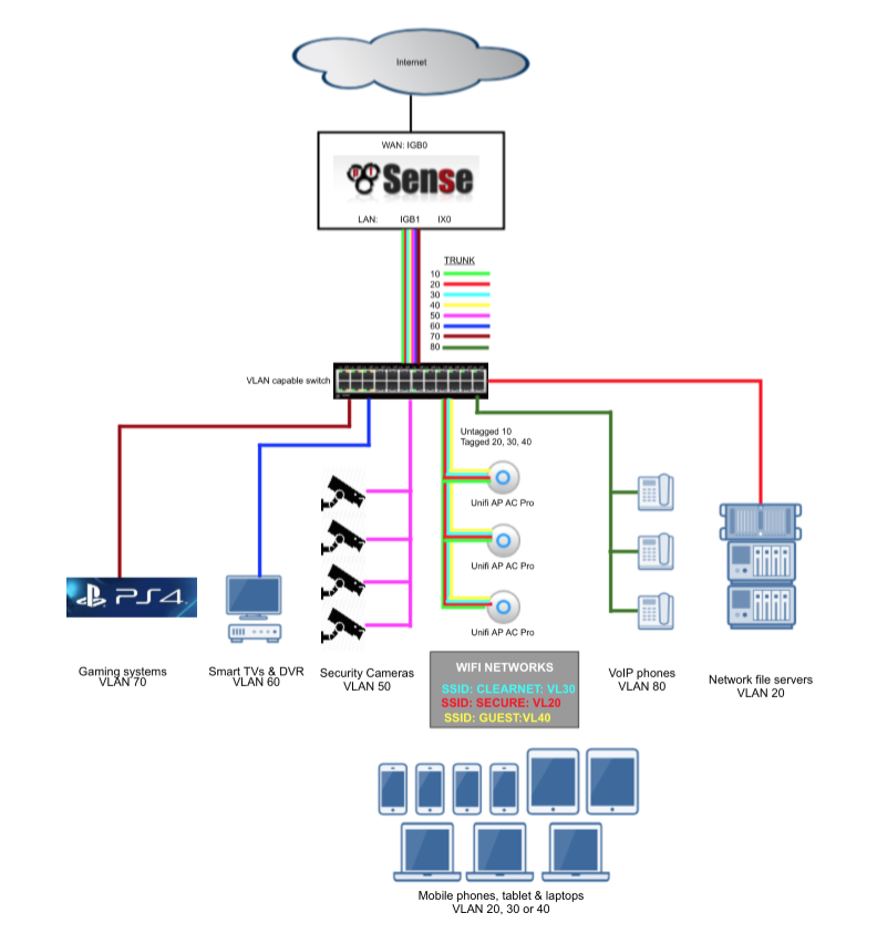
Without VLANs it would be tough to provide enough network interface connections to enable me to apply strict firewall rules and traffic prioritisation to support my needs. For example, the video surveillance system is confined to a single VLAN and has very limited abilities to communicate with devices in other subnets and the internet and my gaming consoles have prioritisation to ensure smooth and problem free network play. These Virtual LAN segments are connected back to pfSense in a ‘router-on-a-stick’ configuration. Its called a ‘router-on-a-stick’ because of the single trunk cable connecting the 802.1Q capable switch to our pfSense router. This enables our switch to handle local subnet traffic switching whilst retaining pfSense to firewall inter-subnet traffic. Some of my file servers and devices generate a substantial amount of traffic and not having to push all this traffic through pfSense allows it to better handle the load it does need to process.
Here’s a diagram to help illustrate my configuration.
Introducing the Netgear GS108E v2
The Netgear GS108E is available cheaply new, and even cheaper used from eBay and makes a useful enough semi-managed switch capable of supporting multiple VLANs. If you decide to go down this route, try and obtain a v3 model as this enables configuration via a web interface as opposed to needing a custom configuration utility which is only available for Windows.
Configure the switch
I’ll walk through how to configure the switch to support the connections outlined in the able below.
| Port | Description | VLANs |
|---|---|---|
| 1 | Trunk to pfSense router | 10, 20, 30, 40 |
| 2 | Access port VL20_VPN LAN subnet | 20 |
| 3 | Access port VL30_CLRNET LAN subnet | 30 |
| 4 | Hybrid port to Ubiquiti Unifi wifi AP | 10 (untagged), 20, 30, 40 |
Connect to the switch
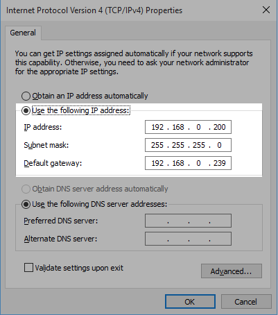
The default IP address of the GS108E is 192.168.0.239. To connect to the switch set your local NIC to a static address in the same subnet as the switches default address, for example 192.168.0.200.
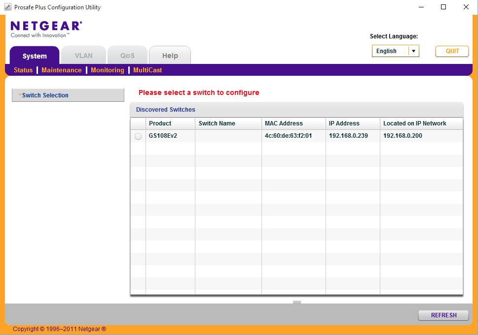
You should now be able to load up the configuration tool, select the GS108E and log in with the default password of password.
Create VLAN tags
First lets add the VLAN ID’s we plan to use.
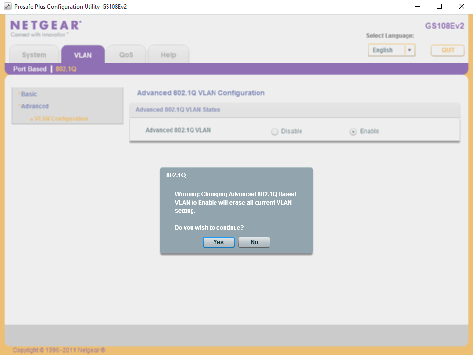
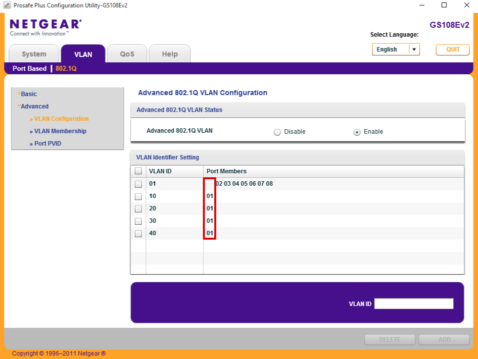
Navigate to VLAN > 802.1Q > Advanced > VLAN Configuration, accept the warnings that enabling the advanced mode will erase existing VLAN settings.
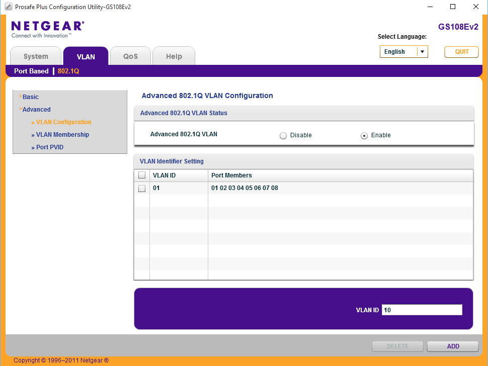
- Set VLAN ID = 10 and select Add.
- Set VLAN ID = 20 and select Add.
- Set VLAN ID = 30 and select Add.
- Set VLAN ID = 40 and select Add.
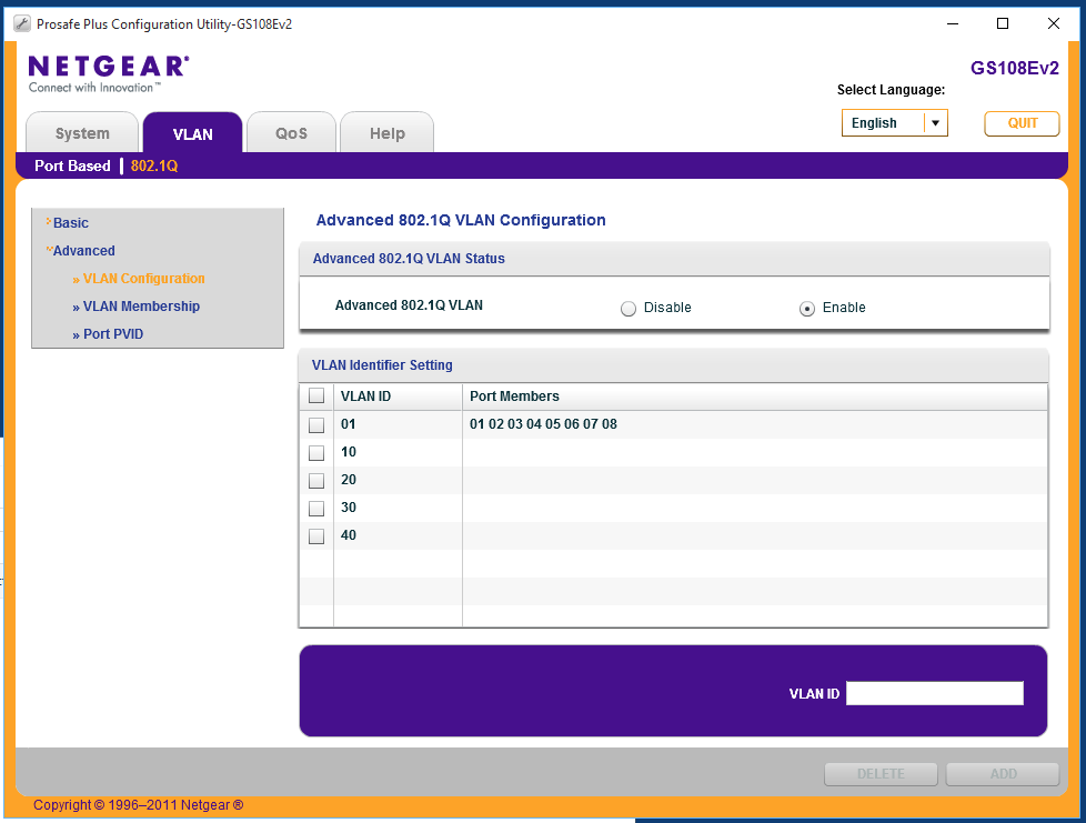
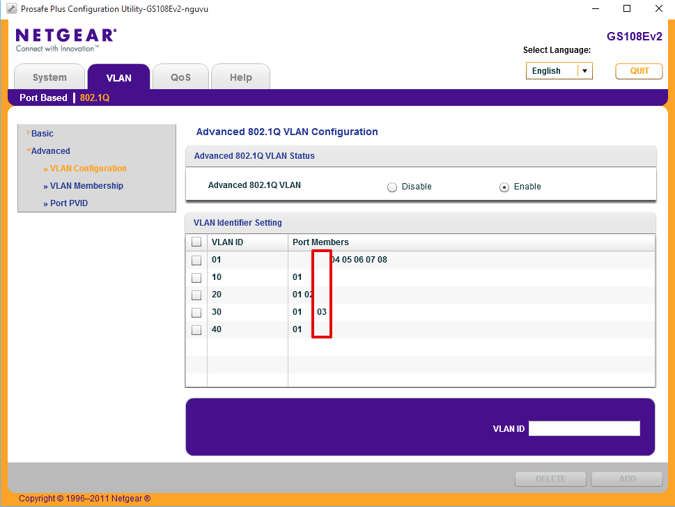
When you have finished your page should look like this.
Configure ports
We’ll now configure each of the ports as outlined above using the VLAN tags we have just setup.
Configure Port 1 for trunk access to pfSense
Port 1 will be used to connect back to pfSense’s parent interface. All VLANs need to be tagged.
Set Port membership
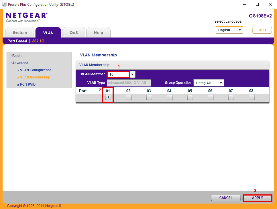
Navigate to Advanced > VLAN Membership and proceed in turn through each of the following steps.
- Set VLAN Identifier = 10
- Set Port 1 = ‘T’ representing TAGGED
- Click Apply
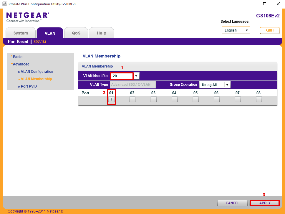
- Set VLAN Identifier = 20
- Set Port 1 = ‘T’ representing TAGGED
- Click Apply
- Set VLAN Identifier = 30
- Set Port 1 = ‘T’
- Click Apply
and finally
- Set VLAN Identifier = 40
- Set Port 1 = ‘T’
- Click Apply
Set port PVID
Navigate to VLAN > 802.1Q > Advanced > Port PVID
- Select Port 1
- Set PVID to 10
- Click Apply
Remove VLAN 1
Now we have set the correct default id, we can remove the original one.
Navigate to VLAN > 802.1Q > Advanced > VLAN Membership
- Set VLAN Identifier = 1
- Set Port 1 to blank, ‘ ‘
- Click Apply
Verify port 1 looks like when complete.
Configure Port 2 for VL20_VPN LAN subnet
This port will be configured to provide a hard wired VPN port. We do this by forcing traffic to be tagged with VLAN id 20.
Set Port membership
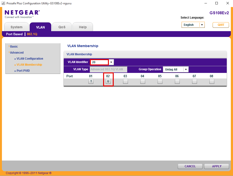
Navigate to VLAN > 802.1Q > Advanced > VLAN Membership
- Set VLAN Identifier = 20
- Set Port 2 = ‘U’ representing UNTAGGED
- Click Apply
Set port PVID
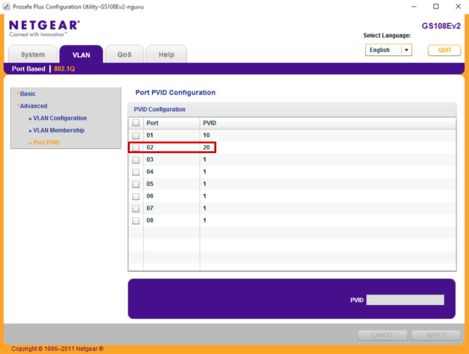
Navigate to VLAN > 802.1Q > Advanced > Port PVID
- Select Port 2
- Set PVID to 20
- Click Apply
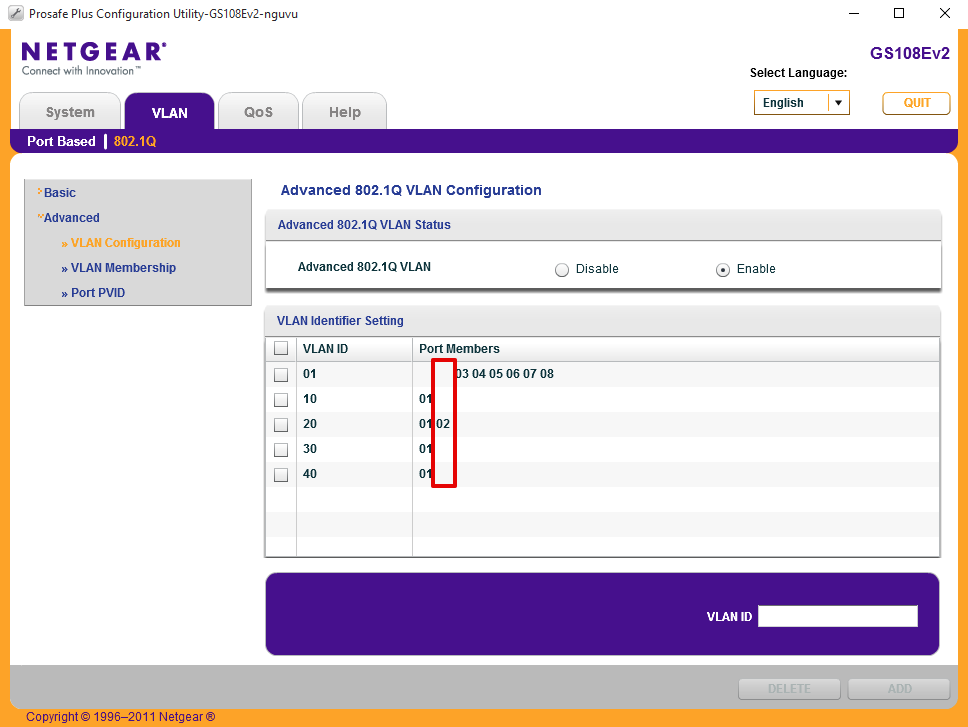
Remove VLAN 1
Navigate to VLAN > 802.1Q > Advanced > VLAN Membership
- Set VLAN Identifier = 1
- Set Port 2 to blank, ‘ ‘
- Click Apply
Configure Port 3 for VL30_CLRNET LAN subnet
Port 3 will be hard coded for access to my CLEAR_NET interface using VLAN id 30.
Set Port membership
Navigate to VLAN > 802.1Q > Advanced > VLAN Membership
- Set VLAN Identifier = 30
- Set Port 3 = ‘U’ representing UNTAGGED
- Click Apply
Set port PVID
Navigate to Port PVID
- Select Port 3
- Set PVID to 30
- Click Apply
Remove VLAN 1
Navigate to VLAN > 802.1Q > Advanced > VLAN Membership
- Set VLAN Identifier = 1
- Set Port 3 to blank, ‘ ‘
- Click Apply
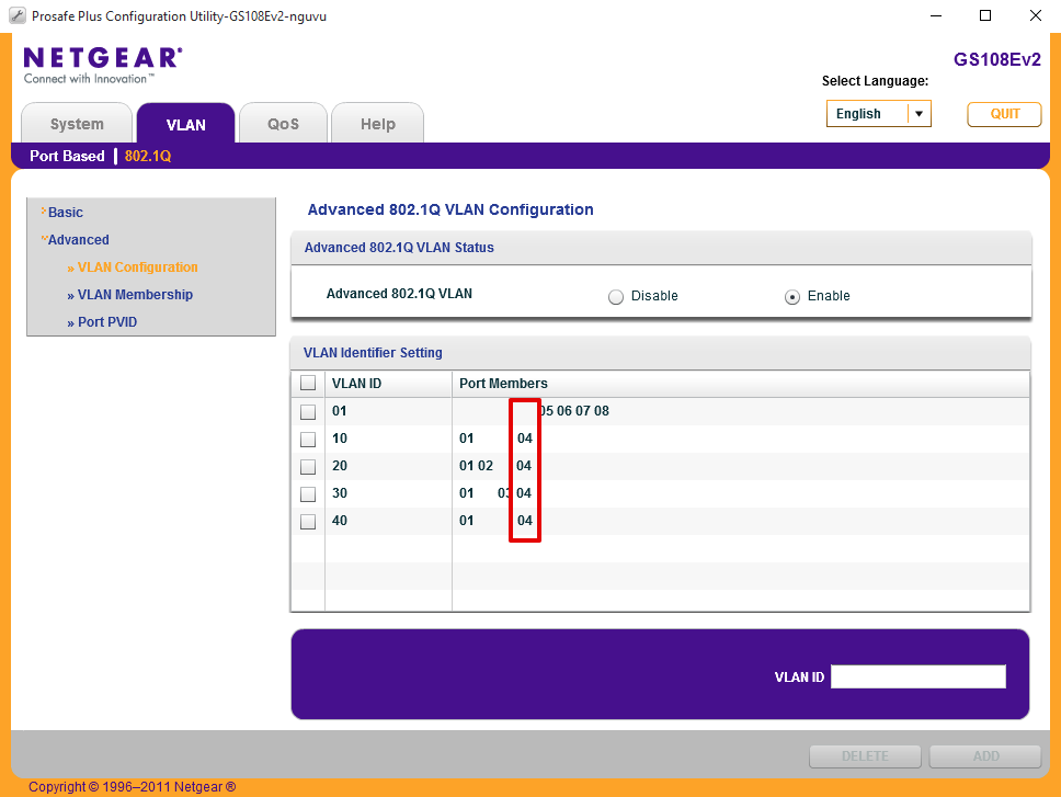
and here’s how the final port configuration should look when done.
Configure Port 4 for Hybrid port access to Ubiquiti Unifi wifi AP
Port 4 will be used to connect a Ubiquiti Unifi access point which is configured to support several VLANs. To support my configuration I require VLAN 10 as untagged, and 20, 30 & 40 tagged corresponding to my VPN, CLEARNET and GUEST SSIDs.
Set Port membership
Navigate to VLAN > 802.1Q > Advanced > VLAN Membership
- Set VLAN Identifier to 10
- Under port 4, click until you see a ‘U’ representing untagged
- Click Apply
then
- Select VLAN Identifier to 20
- Under port 4, click until you see a ‘T’ representing tagged
- Click Apply
then
- Select VLAN Identifier to 30
- Under port 4, click until you see a ‘T’ representing tagged
- Click Apply
and finally
- Select VLAN Identifier to 40
- Under port 4, click until you see a ‘T’ representing tagged
- Click Apply
Port PVID
Navigate to VLAN > 802.1Q > Advanced > Port PVID
- Select port 4
- Set PVID to 10
- Click Apply
Remove VLAN 1
Navigate to VLAN > 802.1Q > Advanced > VLAN Membership
- Set VLAN Identifier = 1
- Set Port 4 to blank, ‘ ‘
- Click Apply
and here’s what the port should look like when done.
Connect and test
If you connect a cable between port 1 of your switch and the port you configured to act as the parent interface on your pfSense router, you should be able to connect a device to ports 2, 3 or 4 and obtain a DHCP address from the DHCP server from the appropriate address pools.
Be mindful of trunk bandwidth
Even though you can go wild and create hundreds of VLAN interfaces and load them up with a multitude of devices, its worth keeping in mind that all the traffic between the switch and the router, i.e the stick, has to go across a single 1 gig UTP cable and therefore is capped at 1gbps. It is possible to use a few techniques to increase this bandwidth and provide additional overhead if required.
Firstly and most cheaply, you can bond a number of RJ45 connections together into a Link Aggregation Group (LAGG), however its worth noting that this won’t break down a single clients traffic into multiple parallel streams as you might expect, traffic is distributed in a round-robin manner across the multiple links so a heavy single threaded connection won’t see any benefit.
Secondly, and my preferred albeit slightly more expensive method, is to migrate the 1gig trunk connection onto a 10gig link. This requires a 10gig network card such as the Intel X520/540 or Chelsio T4/T5 be added to your pfSense router as well as a switch which offers a 10gig uplink. I prefer SFP+ connections over RJ45 due to lower latencies and lower power requirements which reduces electricity consumption and heat which usually requires loud fans to dissipate.
Changelog
28 January 2018
Updated guide to reflect preference to GS108v3 product
Fixed VL10_MGMT tag error.