pfSense router-on-a-stick VLAN configuration with a Cisco SG300
Last revised 28 January 2018.
Contents
- Introduction
- Cisco SG300
- Initial Connection
- General configuration
- Create VLAN IDs
- Configure Interfaces
- Assign switch IP
- Testing
- Power saving notes
- References
Introduction
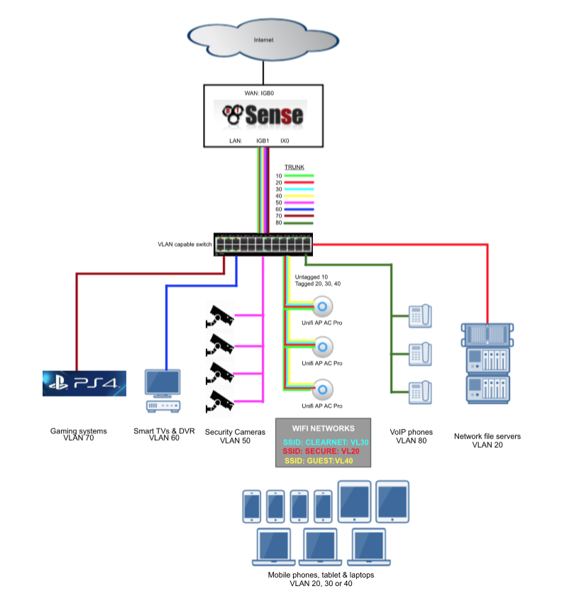
My pfSense baseline guide makes extensive use of VLANs to provide enough network segments to facilitate the segregation of devices into the following categories
| Description | VLAN ID | Subnet |
|---|---|---|
| Management Interface | 10 | 192.168.10.0/24 |
| VPN LAN | 20 | 192.168.20.0/24 |
| ClearNet LAN | 30 | 192.168.30.0/24 |
| Guest network | 40 | 192.168.40.0/24 |
| Security cameras | 50 | 192.168.50.0/24 |
| DMZ | 60 | 192.168.60.0/24 |
| Game consoles | 70 | 192.168.70.0/24 |
| VoIP phones | 80 | 192.168.80.0/24 |
Without VLANs it would be tough to provide enough network interface connections to enable me to apply strict firewall rules and traffic prioritisation to support my needs. For example, the video surveillance system is confined to a single VLAN and has very limited abilities to communicate with devices in other subnets and the internet, my gaming consoles have prioritisation to ensure smooth and problem free network play. These Virtual LAN (VLAN) segments are connected back to pfSense in a ‘router-on-a-stick’ configuration. Its referred to as ‘router-on-a-stick’ because of the single trunk cable connecting the 802.1Q capable switch to our pfSense router. This enables our switch to handle local subnet traffic switching whilst leveraging pfSense to firewall inter-subnet traffic. Some of my fileservers and devices generate a substantial amount of traffic and not having to push all this traffic through pfSense allows it to better handle the load it does need to process.
Here’s a diagram to help illustrate my configuration.
Cisco SG300
The Cisco SG300 switch is an affordable, high-performance, relatively easy to manage device that’s designed specifically for smaller homes and businesses whilst retaining many of the advanced feature sets of other enterprise level products. Although this guide is created on a SG300-10PP which offers fanless operation, 10 gigabit ethernet ports and supports power over ethernet (PoE) the SG300 range includes models with up to 48 ports.
The Cisco SG500 range offer a similar configuration interface and also includes 10 gigabit networking ports on certain models suitable for those needing higher bandwidth capabilities.
Initial Connection
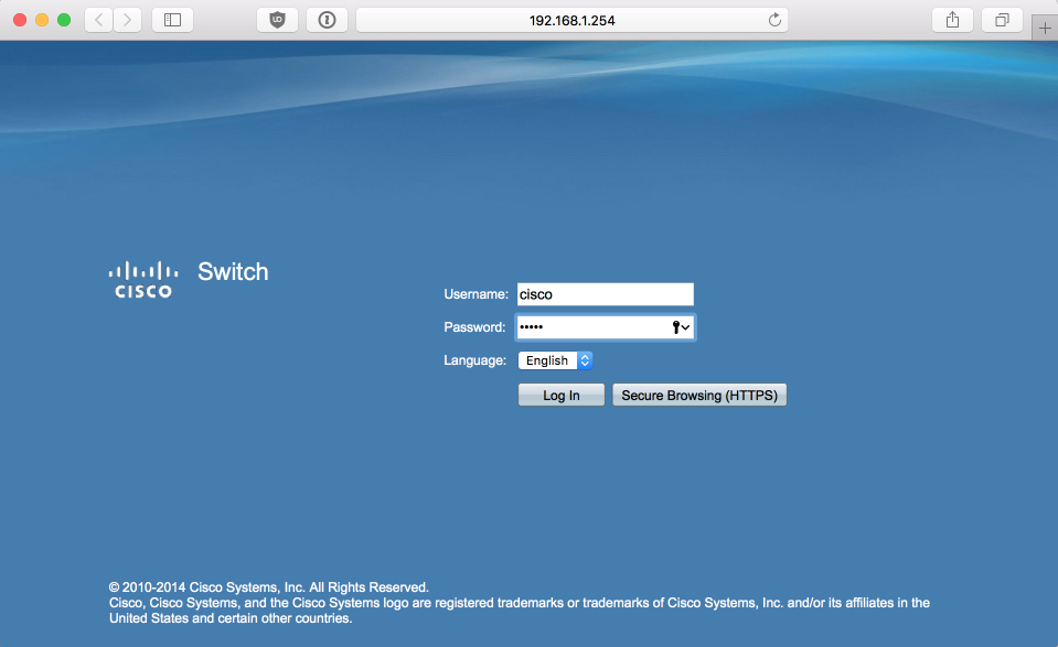
The SG300’s configuration page by default is available on the 192.168.1.254 address. To access it set your PC that you will be using to configure it from into the 192.168.1.x address range, I used 192.168.1.100.
Connect your PC to the SG300’s port 8. You could use another but this keeps the lower ports free and avoids unnecessary complications further on in this guide.
Connect the power and wait for the SG300 to complete its boot process, its takes a little while before you can access the login page at http://192.168.1.254
Login with the default username cisco and password cisco
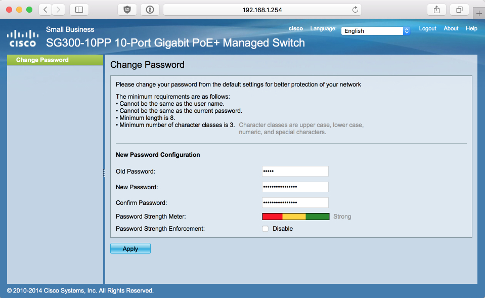
When you log in you will be initially prompted to change the default password, set it to something secure.
General configuration
Enable L3 routing
Enabling layer3 routing will enable us to assign an IP address to our VLAN(s) and ease access post configuration easier. Changing the fundamental processing mode will reset the switch back to its default state.
Navigate to Administration > System Settings and set
- Host name = sg300
- System Mode = L3
Click Apply which will reboot and reset the switch. Once the switch has booted, log back in with default username (cisco) and password (cisco) again where you will be prompted to set your secure password again.
Save & Apply
Create VLAN IDs
Navigate to VLAN Management > VLAN Settings, we will configure the VLAN IDs here required to support my baseline guide. I’ve added some images to help illustrate configuration options and final states.
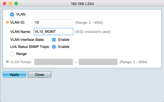
Create VL10_MGMT ID
Click Add
- VLAN ID: 10
- VLAN Name: VL10_MGMT
- VLAN Interface State: Enabled
- Link Status SNMP Traps: Enabled
- Range: [ ]
Click Apply
Create VL20_VPNLAN ID
Click Add
- VLAN ID: 20
- VLAN Name: VL20_VPNLAN
- VLAN Interface State: Enabled
- Link Status SNMP Traps: Enabled
- Range: [ ]
Click Apply
Create VL30_CLRNET ID
Click Add
- VLAN ID: 30
- VLAN Name: VL30_CLRNET
- VLAN Interface State: Enabled
- Link Status SNMP Traps: Enabled
- Range: [ ]
Click Apply
Create VL40_GUEST ID
Click Add
- VLAN ID: 40
- VLAN Name: VL40_GUEST
- VLAN Interface State: Enabled
- Link Status SNMP Traps: Enabled
- Range: [ ]
Click Apply and then Close
When you are done, your VLAN ID table should look like this
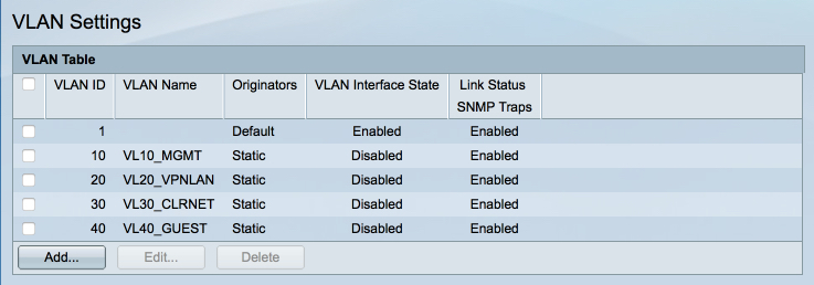
I recommend saving your configuration at this point which is made available through he flashing Save prompt in the top menu bar. Anytime I mention to save I refer to saving the current state to the running and startup configurations.
Configure Interfaces
In this guide we will create the following interfaces:
| Port | Description | VLANs |
|---|---|---|
| 1 | VL10_MGMT access port | 10 |
| 2 | VL20_VPNLAN access port | 20 |
| 3 | VL30_CLRNET access port | 30 |
| 4 | VL40_GUEST access port | 40 |
| 5 | Trunk to Unifi AP (as per my Unifi AP guide) | 10 (untagged), 20, 30 & 40 |
| 6 | Trunk to pfSense | 10, 20, 30, 40 |
Broadly thinking an access mode port can be part of only one VLAN and is typically used to connect to a device or PC. A trunk mode port can be part of one or more VLANs and is typically used to carry information between switches or devices.
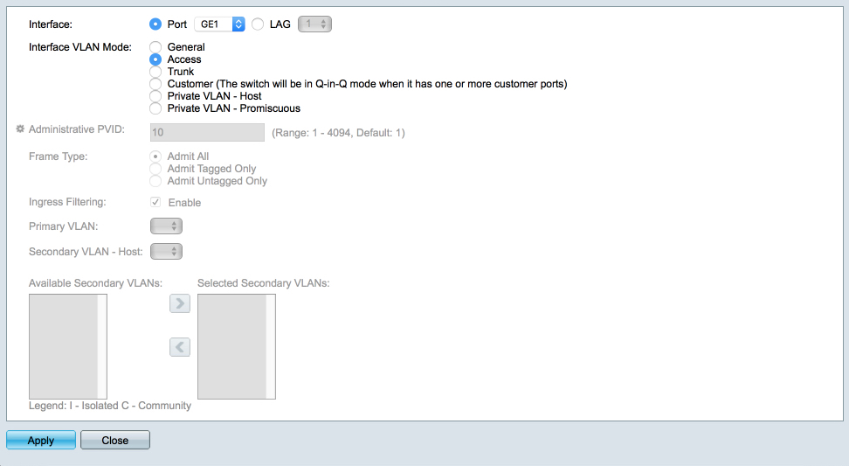
Setup VL10_MGMT access port
Navigate to VLAN Management > Interface Settings
Highlight GE1 and select Edit
- Select ‘Access’
Apply & Close
Navigate to VLAN Management > Port VLAN Membership
Highlight GE1 and select ‘Join VLAN’
- Remove ‘1UP’ (highlight it, and click the left arrow)
- Add ‘10’ as Untagged. (highlight it, and click the right arrow)
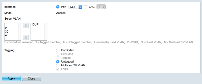
Click on Apply and Close
VL20_VPNLAN access port
Navigate to VLAN Management > Interface Settings
Highlight GE2 and select Edit
- Select ‘Access’
Apply & Close
Navigate to VLAN Management > Port VLAN Membership
Highlight GE2 and select ‘Join VLAN’
- Remove ‘1UP’
- Add ‘20’ as Untagged.
Click on Apply and Close
VL30_CLRNET access port
Navigate to VLAN Management > Interface Settings
Highlight GE3 and select Edit
- Select ‘Access’
Apply & Close
Navigate to VLAN Management > Port VLAN Membership
Highlight GE3 and select ‘Join VLAN’
- Remove ‘1UP’
- Add ‘30’ as Untagged.
Click on Apply and Close
VL40_GUEST access port
Navigate to VLAN Management > Interface Settings
Highlight GE4 and select Edit
- Select ‘Access’
Apply & Close
Navigate to VLAN Management > Port VLAN Membership
Highlight GE4 and select ‘Join VLAN’
- Remove ‘1UP’
- Add ‘40’ as Untagged.
Click on Apply and Close
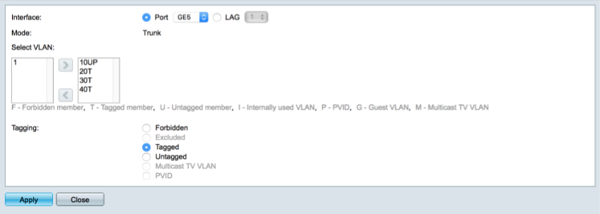
Trunk to Unifi AP
The trunk needs to be configured to provide the management interface on the untagged traffic, and the other SSIDs on tagged packets.
Navigate to VLAN Management > Interface Settings
Verify GE5 is configured as a trunk port
Navigate to VLAN Management > Port VLAN Membership
Highlight GE5 and select ‘Join VLAN’
- Remove ‘1UP’
- Add ‘10’ as Untagged.
- Add 20, 30 & 40 as tagged
Click on Apply and Close
Trunk to pfSense
The trunk needs to carry all the VLANs between our switch and pfSense’s parent interface in tagged packets.
Navigate to VLAN Management > Interface Settings
Verify GE6 is configured as a trunk port
Navigate to VLAN Management > Port VLAN Membership
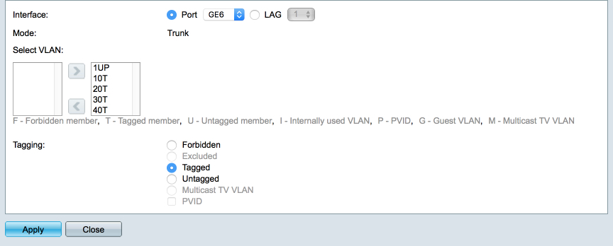
Highlight GE6 and select ‘Join VLAN’
- Leave 1UP present
- Add 10, 20, 30 & 40 as tagged
Click on Apply and Close
When you are complete you Port LAN configuration should look like this
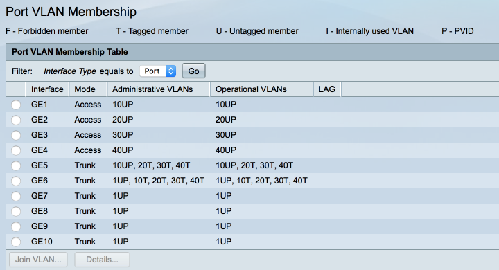
Save the current configuration to the running and startup configurations.
Connect a Cat5e cable between your pfSense trunk interface and port 6 on the SG300 switch.
Assign switch IP address
We will now assign a fixed IP address to our switch via the VL10_MGMT VLAN to enable us to modify the configuration as and when needed.
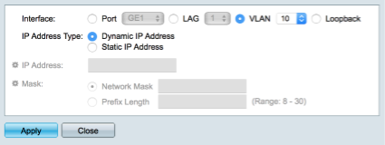
Navigate to IP Configuration > IPv4 Interfaces
Click Add
- Select VLAN 10
- Select Dynamic IP address
Click Apply
Don;t worry at this point you will lose contact with the SG300. Setting the IP address of the VL10_MGMT interface overrides the default 192.168.1.254 address we have been using so far. Before we can reconnect, we will configure pfSense to provide a fixed IP address via a Mac address reservation. I like to assign fixed IP addresses to my infrastructure hardware and I prefer to do it through Mac reservations within pfSense. This has a benefit of maintaining accurate routing tables and provides me with a centralised resource to keep track of current reservations.
Log into pfSense and navigate to Statistics > DHCP reservations where you will hopefully see our current SG300 IP address assignment as made by the DHCP server, in the example below you can see the SG300 has acquired the 192.168.10.162 address.
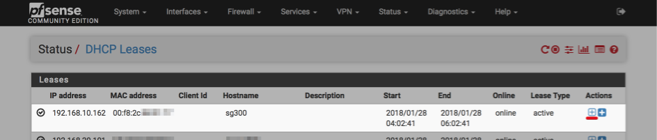
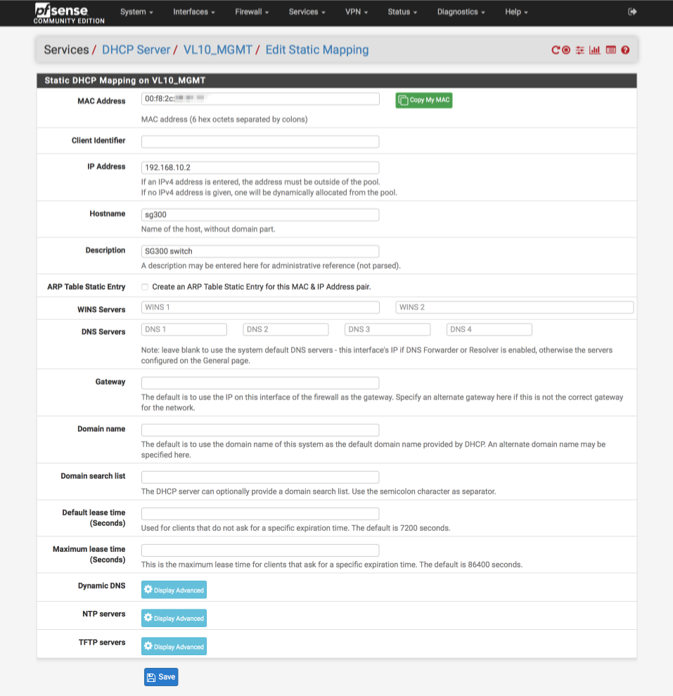
Click the ‘plus’ symbol (underlined with red above) to assign a static IP address, I’m using 192.168.10.2.
Its now worth rebooting your SG300 switch to ensure it picks up the new IP address we just allocated for it.
Testing
Disconnect your PC from the SG300 switch and reconfigure it to obtain an IP by DHCP.
Connect your PC to port 1 and assuming everything has worked you should be awarded an address in the VL10_MGMT subnet of 192.168.10.x.
Verify ports 2 provides an address in VL20_VPNLAN range, i.e 192.168.20.x
Verify ports 3 provides an address in VL30_CLRNET range, i.e 192.168.30.x
Verify ports 4 provides an address in VL40_GUEST range, i.e 192.168.40.x
Connect your Unifi AP to SG300’s port 5 and verify you can connect to each SSID and are awarded a corresponding IP address.
Verify you can access the SG300 web configuration page at 192.168.10.2 from VL10_MGMT, VL20_VPNLAN & VL30_CLRNET. You should no able to access it from VL40_GUEST due to our pfSense firewall configuration blocking access to other internal networks.
Configuration notes
Power saving mode
The Cisco SG300-10PP is equipped with some useful power saving technology but I have previously found some issues with PoE being enabled with certain devices. If you find you are having problems try disabling the power saving features to eliminate this possibility.
To disable navigate to Port management > Green Ethernet > Properties and set
- 802.3 Energy Efficient Ethernet (EEE) = Disabled
Apply