pfSense multi-WAN failover
Last revised 7 March 2021.
Contents
- Introduction
- Failover options
- Cradlepoint CBA-850 Configuration
- Cradlepoint CBA-850 Installation
- pfSense configuration
- Testing
- References
Introduction
As more homes and business rely on the internet than ever, a reliable internet connection is pertinent to avoiding downtime in the event that internet connection is disrupted. Landlines are unfortunately vulnerable to disruption, and no matter how reliable your internet service provider is, having a backup, or failover, connection is useful to avoid disruptive downtime.
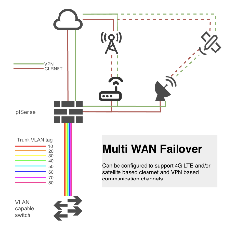
Failover is the ability to seamlessly switch to a reliable backup system when a primary system fails minimizing disruption to systems and users. Backup communication systems can be provided with additional broadband connections, satellite links, or cellular based systems. This guide will focus on configuring pfSense and supporting hardware to provide failover protection using a cellular 4G LTE connection.
Failover options
In considering failover options, I prioritised reliability and performance over cost or ease of installation. This does not mean this has to be expensive or difficult to install, but if going to the cost and effort of providing redundant communication channels, having them be available when needed, and fit for intended purpose is a requirement.
4G LTE based failover
4G LTE based cellular connections are available cheaply and can offer reliable and reasonable performance given suitable proximity and line of sight to cellular towers. There are a number of devices that can enable to use of 4G.
Onboard PCI / m-sata based modems
There are motherboards that support M.2 B-Key modems directly, for example the Supermicro’s X11SDV pictured below.
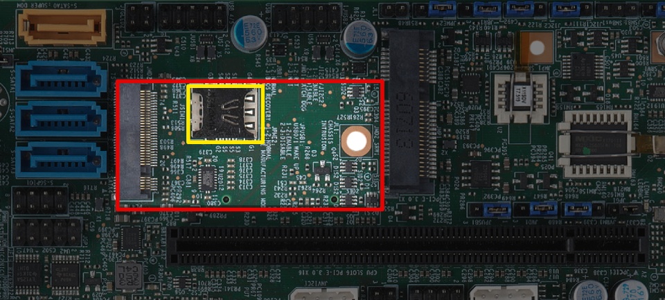
Although this may seem ideal, there are a couple of drawbacks to consider.
- Optimal antenna location for reception of cellular signals is unlikely to be inside where the router itself is installed. This will likely require longer coaxial runs with associated signal losses. Even high quality Times Microwave LMR200/LMR400 coax will introduce undesirable signal attenuation.
- FreeBSD (pfSense foundations) has limited MODEM support.
USB modems
USB modems suffer with similar drawbacks to onboard devices, i.e
- Usually physically connected to the router away from the optimal antenna location necessitating longer coaxial cables than ideal.
- Limited FreeBSD driver support.
- Often do not provide connectivity to support external antennas.
- USB is not widely considered a robust protocol.
4G router / Ethernet adapters
There are dedicated enterprise class 4G LTE routers available that can be configured to convert a 4G LTE signal to a standard ethernet RJ45 based connection, ideal for feeding into pfSense. I currently recommend the Cradlepoint CBA-850 for the following reasons:
- Presents as a regular modem to pfSense with no dependency on FreeBSD driver support
- Supports wide range of modems suiting your local needs regarding channel capabilities
- High quality enterprise grade product that runs cool and has been 100% stable over many years of service
- Powered by power over ethernet (PoE) simplifying external installation
- Can be situated adjacent to the 4G antennas minimizing coaxial cable length and associated signal attentuation.
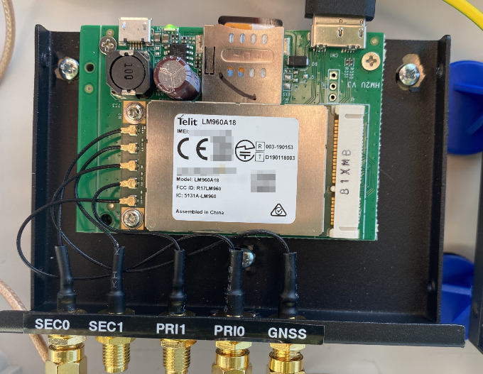
- Compatible with a wide range of modems including Sierra Wireless (EM7455, EM7511, EM7565) and Telit (LM960A18).
Retail pricing on these routers new was in the region of $600 reflecting the enterprise nature, however, they are now available as cheaply as $50 refurbished from retailers or other popular online used sales portals.
Cradlepoint CBA-850 Configuration
The CBA850 has two primary modes of operation. It can perform primary routing functions, or as this guide will configure, function simply as a modem using IP Passthrough (bridge Mode) to the primary pfSense router, essentially acting as a ‘cellular-to-ethernet’ adapter.
In passthrough mode a public IP address will be passed through to the connected device so its important to connect to a secure network device such as a router or firewall and not direct to a laptop or other unprotected device. This mode also removes the need to use an unnecessary Network Address Translation (NAT) layer and also removes the need to configure any DMZ or port forwarding settings on the Cradlepoint.
First time setup
It may simplify problem resolution to configure the CBA850 in a physically easy to access location prior to any final external installation.
Connect your PC to the LAN 1 Ethernet port on the CBA850. LAN 2 POE is by default set to IP Passthrough and requires a valid internet connection before you can access the router by a different IP address than LAN 1.
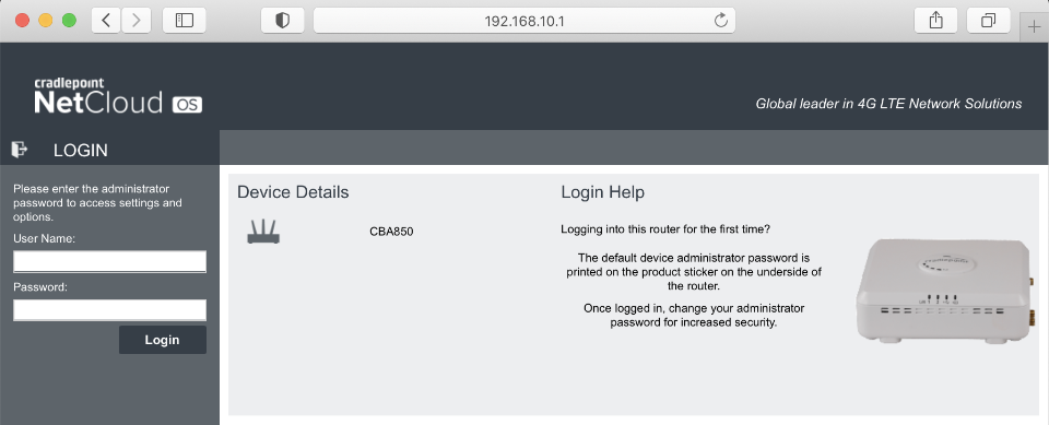
Connect your PC directly to your CBA-850 and navigate to 192.168.10.1. You can login with initially with the default username of admin. The default password is last 8 digits of the units MAC address, also printed on underside of the modem.
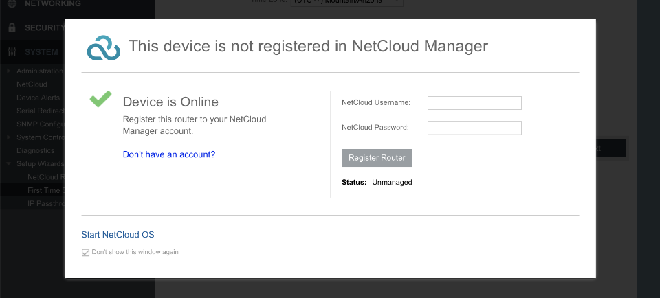
Bypass NetCloud
From April 2019 Cradlepoint moved towards a cloud-based subscription service called NetCloud. This is not a requirement for our use case.
Netcloud username: blank
Netcloud password: blank
Dont show this window again
Click Start Nextcloud OS
Wizard setup
Step 1 of 3
Administrator password: somethingSuperSecure
Timezone: as per your locale
Click Next

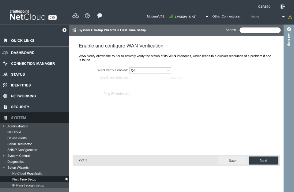
Step 2 of 3
WAN verify enabled: off
Click Next
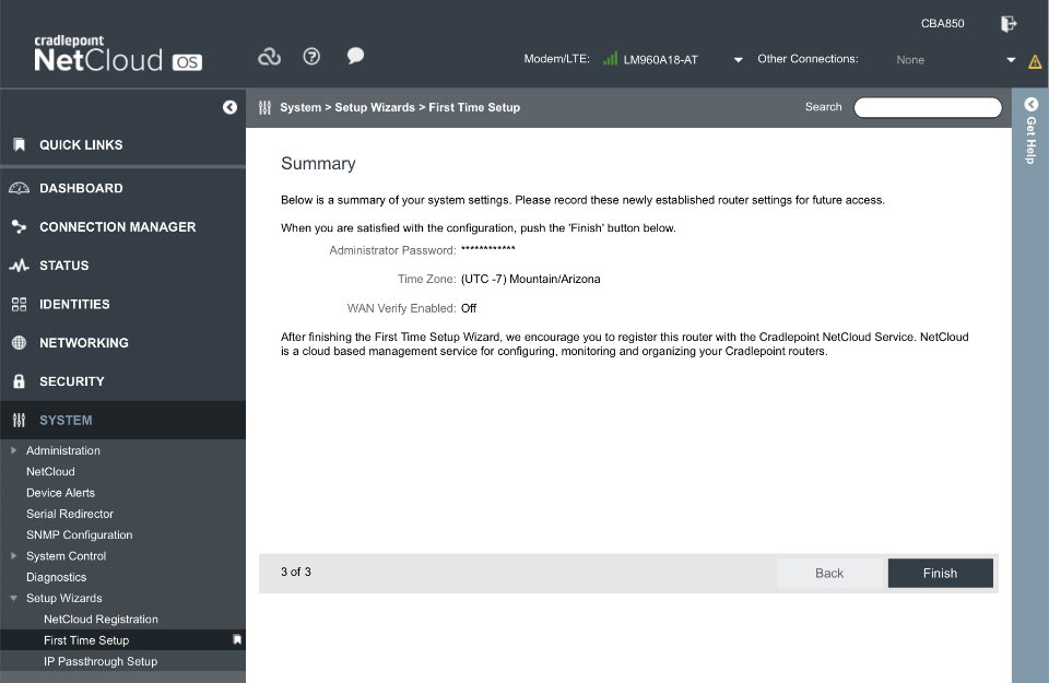
Step 3 of 3
Verify Settings and Click Finish
Update firmware
Cradlepoint recently moved (back) towards a cloud-based subscription service which was implemented in NCOS software releases post v7.0.50. Use NCOS v7.0.50 and avoiding updating further to retain functionality without needing to subscribe to the paid NCOS service.
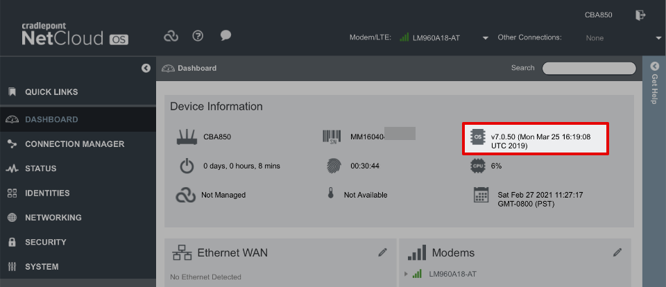
Navigate to System > NetCloudOS > Manual NCOS Upload and upload firmware that can be obtained from the following links.
- NetCloudOS v7.0.50 from Cradlepoint connect
- Modem firmware (MC400 etc) Customer Cradlepoint
Modem configuration
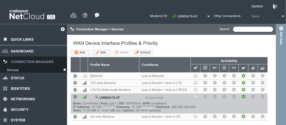
If there is a valid SIM card and appropriate firmware installed your modem should connect.
If there is a need to configure the modem APN or bands, it can be performed through the device’s console at System > System Control > Device Options > Device Console.
Verify the modem is connected as indicated by a green icon in the header bar and in the connection manager dialogue.
Common carrier APN’s are
- AT&T:
broadband - Verizon:
vzwinternet - T-Mobile:
fast.t-mobile.com - Sprint:
r.ispsnorn.ispsn
System
Logging
Once configured and functional, consider reducing the amount of logging by navigating to System > Administration > System Logging
- Logging Level: Critical
Click Save
Networking
Administration
Set system identifier by navigating to System > Administration > Local Management
- Local Domain: local.lan
- system identifier: CBA850
Click Save
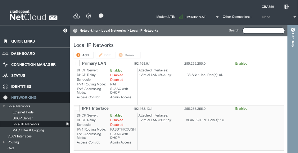
Interfaces
Primary LAN1 is configured with NAT and administrator access. This enables a connection through LAN1 port for debugging purposes should LAN2 fail to function for any reason.
The IPPT Interface is configured to operate in IP Passthrough mode with administration access available at 192.168.13.1.
Navigate to Networking > Local Networks > Local IP Networks
IPPT interface:
Select Edit
- General
- Enabled:
- Name: IPPT Interface
- Hostname: cp (default)
- IPv4 settings
- IPv4 IP: 192.168.13.1
- Netmask: 255.255.255.0
- IPv4 routing: IP Passthrough
- Subnet selection: Force 24 subnet
- Ethernet cycle time: 10
- IPv6 settings
- Address Source: Delegated
- Interfaced
- Selected: VLAN: 2-IPPT: Port(s): 1U
- Access Control
- UPnP Gateway:
- Admin:
- IPv4 DHCP
- DHCP server =
- Range start: Auto
- Range end: Auto
- Lease Time = 3600mins
- Custom options:
- Enable DHCP Relay:
- IPv6 Addressing
- Configuration Mode: SLAAC with DHCP
- DHCP Range Start: 1
- DHCP Range End: Auto
- Lease Time: 3600 mins
- Schedule
- Enable Schedule Service:
Click Save
After saving, the Local IP Networks should look like
Cradlepoint CBA-850 Installation
Although it’s possible to use the CBA-850 inside a building with the included antennas, an optimal signal is available when using an external antenna and minimally attenuated by the use of short coaxial cables to an adjacently mounted CBA-850.
To protect the CBA-850 from the elements install it into a robust weather proof box such as one of those from WiFix. The image below is a medium enclosure (27.2 x 27.6 x 9.6cm / 10.7 x 10.8 x 3.8inch) for reference.
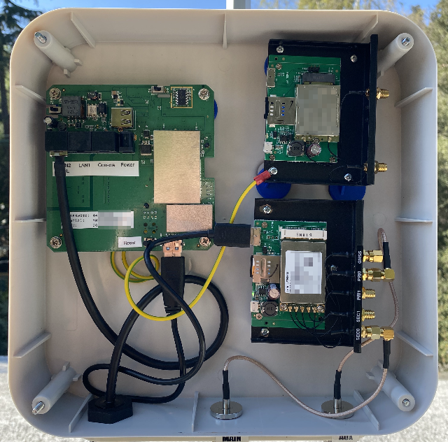
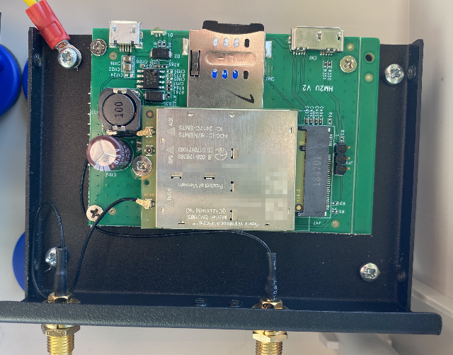
Although a number of official Cradlepoint CBA-850 modems are available, cost effective 3rd party modems are usable with an appropriate USB sled. The images below shows both a USB>M2 and USB>PCIe based modem sled that I used whilst testing various modems.
Antennas
Antennas are a complicated topic and are outside the scope of this article. Optimal selection will be heavily influenced by your geographical location and relative proximity to the broadcast towers.
Two invaluable web sites that can help understand how to maximize signal reception include:
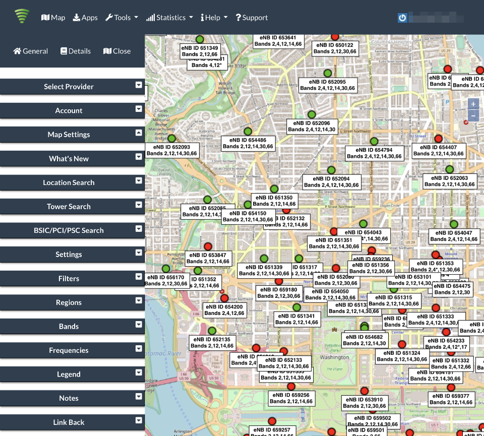
Cellmapper
Cellmapper offers insight as to what cellular towers are within your vacinity, and what carriers and bands are available on each.
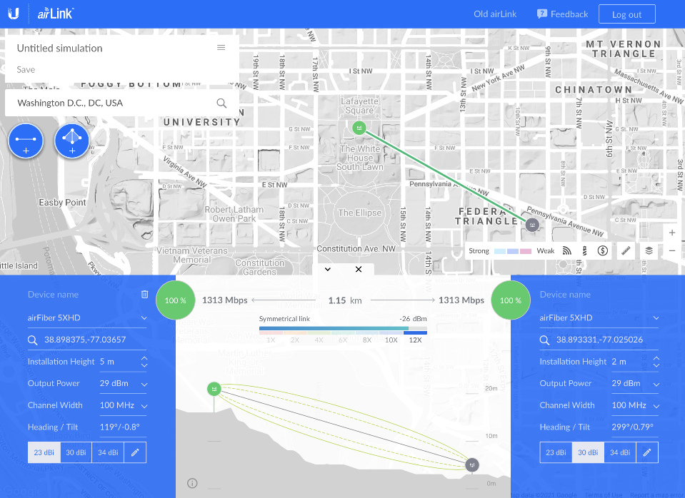
Ubiquiti airLink
airLink offers insight into the land topology between you and the cellular tower you are connected to.
pfSense configuration
This section will build on the pfSense baseline guide setup. This section aims to cover the major services that require configuring to enable failover functionality. However, there may be unique local settings that the reader will need to consider, for example, if they have followed other guides that implement redundant VPN connections.
Create failover WAN Interface
Navigate to Interfaces > Assignments
Select an available network port that the Cradlepoint modem will be connected to, click Add.
Click on the newly created OPTx label to configure the port as follows:
General Configuration
- Enable Interface:
- Description: WAN3
- IPv4 Configuration: DHCP
- IPv6 Configuration: None
- MAC Address: blank
- MTU: blank
- MSS: blank
- Speed and Duplex: Default
- Block
Reserved Networks
- Block private networks:
- Block bogon networks:
Save
Create failover VPN
A second VPN connection will be required that originates its connection on the WAN3 interface previously created.
The originating interface can be edited within the VPN client configuration.
DNS
Add the ability to resolve system and DNS Forwarder based queries over the failover WAN3 connection.
Navigate to System > General Setup
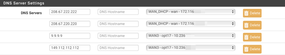
Add two additional servers under the existing WAN_DHCP based primary and secondary servers. This example uses the Quad9 servers but can be substituted.
- 9.9.9.9
- 149.112.112.112
Set the gateway of these two servers to be the failover WAN3 interface. When complete your DNS server settings should look like this.
Routing
Gateway
Add a gateway for failover WAN3 traffic. This example uses a Quad9 server for monitoring latency.
Navigate to System > Routing > Gateways & click Add.
- Disabled:
- Interface: WAN3
- Address family: IPv4
- Name: WAN3
- Gateway: blank
- Gateway Monitoring:
- Gateway Action:
- Monitor IP: 149.112.112.9
- Force state:
- Description: Interface WAN3 Gateway
Save
Default gateways
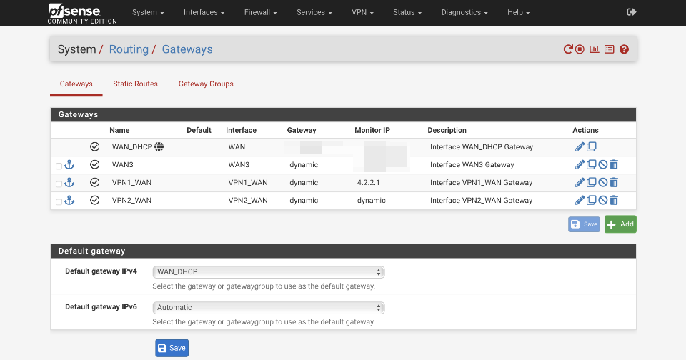
Navigate to System > Routing > Gateways
- Default gateway IPv4: WAN_DHCP
- Default gateway IPv6: Automatic
Save
When complete the gateway configuration should look similar to this
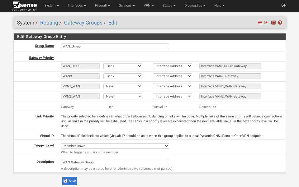
Gateway Group - WAN
Create WAN_Group gateway group.
Navigate to System > Routing > Gateway Groups & click Add.
- Group Name: WAN_Group
- Gateway Priority:
- WAN_DHCP: Tier 1
- VPN_WAN: Never
- WAN3: Tier 2
- Link Priority:
- Virtual IP:
- Trigger level: Member Down
- Description: WAN Gateway Group
Click Save
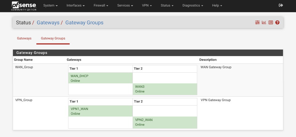
Gateway Group - VPN
A gateway group will be required for the VPN failover also. When the primary WAN_DHCP connection drops, VPN1_WAN will also be dropped. This VPN failover group will failover the VPN1_WAN tunnel to the secondary VPN2_WAN gateway available via the WAN3 connection.
Navigate to System > Routing > Gateway Groups & click Add.
- Group Name: VPN_Group
- Gateway Priority:
- WAN_DHCP: Never
- WAN3: Never
- VPN1_WAN: Tier 1
- VPN2_WAN: Tier 2
- Link Priority:
- Virtual IP:
- Trigger level: Member Down
- Description: VPN Gateway Group
Click Save
Verify this is correct by navigating to Status > Gateways > Gateway Groups
Static routing for Cradlepoint CBA850 access
Once the modem connects pfSense will be allocated an external IP address. In order to be able to access the Cradlepoint CBA850 configuration page a static route is required to direct traffic out the appropriate port.
Navigate to System > Routing > Static Routes & click Add.
- Destination network: 192.168.13.1 / 32
- Gateway: WAN3
- Disabled:
- Description: CBA850 route
Save
NAT
Additional NAT rules will be required to enable traffic to egress failover gateways (WAN3 & VPN2_WAN) from the local subnets. Although this guide only provides an example for the LAN interface, you will need to consider all your subnets and external traffic flows for a fully robust system.
LAN
Navigate to Firewall > NAT > Outbound
Ensure ‘Manual outbound NAT rule generation` is selected.
Click ‘↴+’
Advanced Outbound NAT Entry
- Disabled:
- Do not NAT:
- Interface: WAN3
- Address Family: IPv4
- Protocol: any
- Source
- Type: Network
- Source Network: 192.168.1.0 / 24
- Source port: Blank
- Destination
- Type: Any
- Address: Blank
- Destination Port: Blank
- Not :
Translation
- Address: Interface Address
- Port or Range: blank
- Static Port:
Miscellaneous
- No XMLRPC Sync =
- Description = LAN to WAN3
Click Save & Apply
Firewall rules
The firewall rules are configured as per the baseline guide for non-local traffic to egress to the internet via the default gateway. The rule responsible for this needs updating to egress traffic via the WAN_Group so traffic will egress the Tier 1 gateway, or if unavailable, egress out the failover tier2 connection. When the tier1 gateway is available again, traffic will revert to egress via the primary gateway once again.
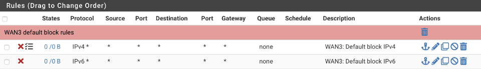
WAN3
Navigate to Firewall > Rules > WAN3
Create default block for IPv4 (with logging) & IPv6 (sans logging)
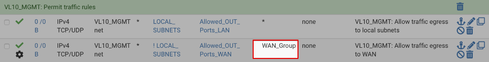
VL10_MGMT egress
Navigate to Firewall > Rules > VL10_MGMT
Click on the pencil icon by the WAN egress rule and change the gateway to be the WAN_Group. The option is located under the advanced options section which is hidden by default.
Before rules
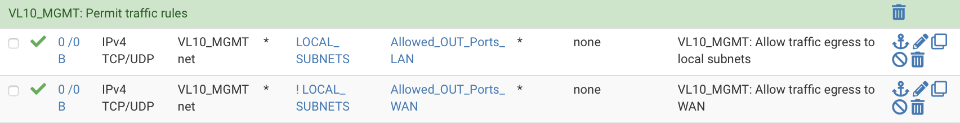
and after editing
Adjust the non-local egress on your other subnet interfaces.
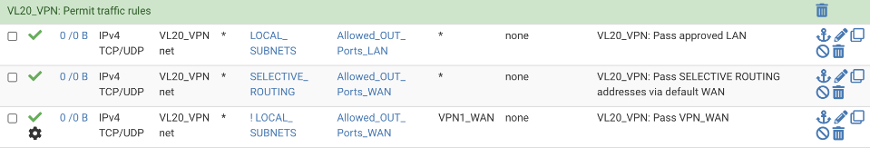
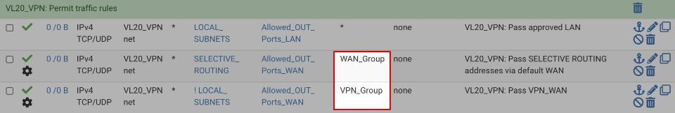
VL20_VPN egress
VL20_VPN supports traffic egress via both the regular and VPN gateways. Both rules require updating to support failover gateways.
Navigate to Firewall > Rules > VL20_VPN
Click on the pencil icon by the WAN egress rule and change the gateway to be the WAN_Group.
Click on the pencil icon by the VPN egress rule and change the gateway to be the WPN_Group.
Before rules
and after editing
Testing
Navigate to Status > Gateways > Gateway Groups and verify the primary gateway enters a degraded state when the primary connection is interrupted. Verify the primary gateway returns to service when they primary connection is restored. There is a smoothing function applied to the gateway status to prevent flapping that will prevent the gateway being restored immediately.
Failover tuning
If the gateway isn’t appropriately responsive to service levels, tuning gateway thresholds may be necessary.
Navigate to System > Routing and click the pencil icon next to a gateway.
Under the Advanced Gateway Settings adjust the thresholds for packet loss, latency, down time, and probing intervals that control when the gateway is considered up or down.
Member Down: Marks the gateway as down only when it is completely down, past one or both of the higher thresholds configured for the gateway. This catches worst case failures, when the gateway is completely unresponsive, but may miss more subtle issues with the circuit that can make it unusable before the gateway reaches that level.
Packet Loss: Marks the gateway as down when packet loss crosses the lower alert threshold (See Advanced Gateway Settings).
High Latency: Marks the gateway as down when latency crosses the lower alert threshold (See Advanced Gateway Settings).
Packet Loss or High Latency: Marks the gateway as down for either type of alert.
DNS leaks
I recommend running the full suite of DNS tests from the baseline guide to ensure full functionality and that no privacy compromising leaks have been introduced in both primary and failover states of operation.