pfSense 2.1 setup with AirVPN
Published 1 November 2014.
NOTE: Please see the updated pfSense 2.3 guide here which makes use of the DNS Resolver and VLAN’s as it improves on this guide in several areas.
Introduction
I wanted to put up a basic pfSense VPN configuration which can be used as a foundation for some of the other guides I’ve posted. There are a few VPN configuration guides published already but the best one by far in my opinion is the one created by ‘pfSense_fan’ over on the AirVPN forums. I’ve built upon his base configuration to enable local host lookups and WPAD/PAC auto configuration of desktop and tablet clients. I’m hoping to expand this collection of how-to’s to cover the additional of potential home network devices such as NAS’s and DMZ’s.
Requirements
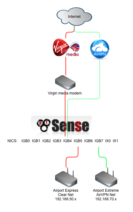
I wanted the ability to provide dual local networks, one being an unencrypted ‘clearnet’ connection, the other being VPN encrypted. It was a requirement to be easily able to easily jump between these two networks without recabling my routers or wifi access points. To support this setup you’ll need your own AirVPN subscription and a router with at least three network ports.
Why AirVPN?
There are a number of VPN providers on the market but the reasons why I went with AirVPN are primarily:
- Its operated by activists interested in defence of net neutrality, privacy and censorship.
- Ability to surf anonymously with no logging or monitoring
- Good security, OpenVPN based, 4096 bit RSA key-sizes & AES-262-CBC data channel
- Internal DNS with anti-ICE/ICANN censorship.
- Supports port forwarding / DDNS.
- High performance servers in multiple countries
- No traffic limits, no speed filtering
- Three simultaneous connections
- Accepts bitcoin
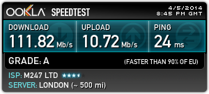
I found AirVPN speeds were best in class when I benchmarked a few of the other top ranked providers earlier this year. I’ve now been with AirVPN for nearly a year and have suffered downtime counted in single digit minutes.
If you haven’t got an Air subscription, you can take out a subscription here.
Specification
I’m using a Virgin Media 120mbps service that supports 120mbps download and 10mbps upload capabilities. Engaging VPN encryption reduces throughput by approximately 10%.
The following diagram illustrates the basic network topology we’ll end up with at the end of this guide.
Hardware selection
Although it is possible to build a pfSense router from pretty much any old hardware, I wanted to build something which was powerful enough to handle VPN encryption on a 100mbps+ connection with minimal losses with headroom to spare in order to run some additional security and packet filtering packages (i.e Snort, Suricata etc). I also plan on this router being in production use for a number of years so wanted to ensure it was able to manage future requirements as my Internet connection increases.
I settled on the following hardware:
Motherboard: Supermicro A1SRM
Processor: Intel Atom processor C2758 2.4Ghz, 8-core, 20W
RAM: 16GB (2x8GB) DDR3 1600Mhz
System Disk: Intel 40GB 320 Series SSD 2.5”
Case & PSU: DV Industrial DS27 Janus 2U server case with 50W fanless PSU
Depending on your networking requirements, you may or may not need require additional network interfaces. In my case I’ve installed two additional network interface cards: Intel X520 2x10gbps and Intel i350-T4 4x1gbps
NB: I’ll try and find some time to write some thoughts on the reasons why I selected the above hardware and document the build process.
Install pfSense
Download and create bootable pfSense USB based installer
Download latest pfSense image from here. I used the AMD64, Live CD with installer on USB.
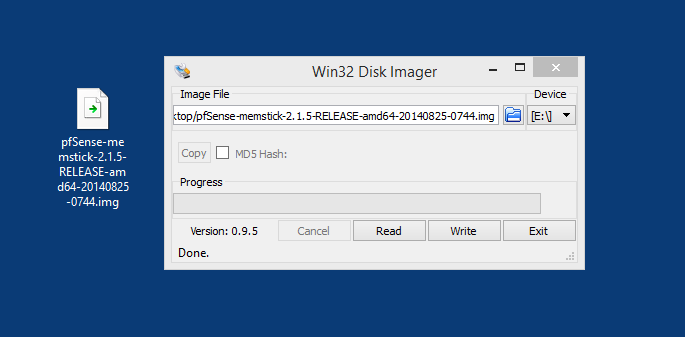
Burn the .img file to a USB stick with at least 2GB of space. I used Windows 8.1 and ‘Win32 disk Imager’ which can be downloaded from here.
Begin the install
Insert the USB stick into a motherboard port.
Use the BIOS boot menu (F11) or set the BIOS to prioritise booting from USB.
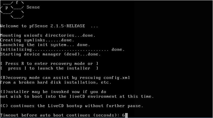
After a few minutes you’ll be prompted to press ‘I’ to launch the installer which will install pfSense to the system hard disk.
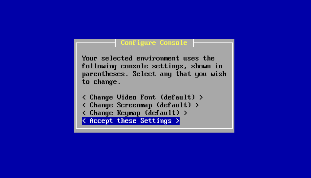
Accept the configuration console screen settings.
If you are installing to the first hard disk in the system, select the Quick/Easy install option. The custom option allows you to select other drives or customise the geometry which is beyond the scope of this article.
When prompted to select a kernel, select Symmetric processing (multi-core).
At the Reboot screen, remove the USB key and allow the system to boot from the system hard drive. Eventually you will be presented with a ‘Welcome to pfSense’ menu, let the timer run out or select the default option to boot if you are impatient.
Create interfaces
When pfSense boots it will display the detected NICs and prompt you to configure your interfaces. Depending on which cards you have installed (and supported) your screen may look slightly different to mine.
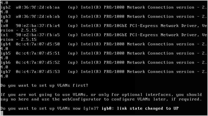
When asked if you want to configure VLANs, enter [N].
When asked for WAN and LAN ports, you can either enter their names at or use the automatic mode to detect the port. The automatic mode can reduce confusion for new users and requires a network cable to be inserted into each port in turn.
When asked for the WAN port, enter the name of the port which will be connected to the internet modem, in my case this was [igb4].
When asked for the first LAN port, enter the name of the port which will be connected to the local network. in my case this was [igb5].
You can configure additional ports here or later within the GUI interface. I went on to add the rest of my interfaces at this stage. My NICs enumerate with the motherboard ports at igb4-7, my additional Intel quad port i350s are igb0-3 and my Intel x520s ports are ix0-1.
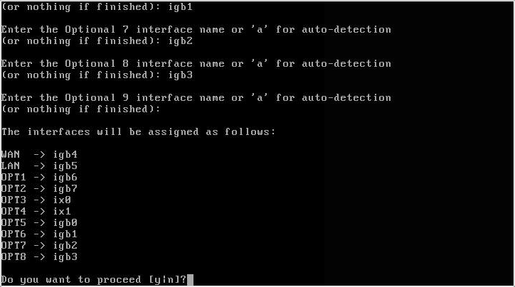
When you have configured the remaining ports, you will be prompted to confirm your selection and continue. Enter [Y] when you are happy or [N] to restart the configuration stage.
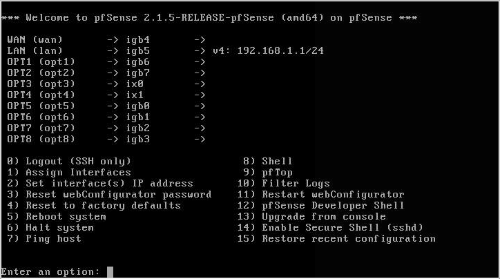
At this stage you can now enter the web GUI.
Initial configuration
Log into web interface with your browser at address displayed on the console, typically 192.168.1.1. You may need to configure your clients interface with a specific IP address in the same subnet to connect as pfSenses DHCP server is not activated and able to auto configure clients yet.
Log in with default credentials: username ‘admin’ and password ‘pfsense’.
Enter the following information in the General Information settings. We’ll use OpenDNS servers initially (208.67.x.x).
- Hostname = pfsense
- Domain = yourname.local.lan (customise appropriately but avoid calling it ‘local’ as this causes issues later)
- Primary DNS = 208.67.222.222
- Secondary DNS = 208.67.220.220
- Allow DNS overridden by DHCP/PPP on WAN = [ ] unticked.
- Click Next
Time server information
- 0.pfsense.pool.ntp.org
- Timezone = set according to your location
- Click Next
WAN configuration
- Type = DHCP
- Click Next
Configure LAN Interface
- LAN IP Address = 192.168.1.1
- Subnet mask = 24
- Click Next
Set Admin GUI password
- Admin password = set something secure and don’t forget it.
- Click Reload
Congratulations, you’ve completed the first stage of configuring pfSense.
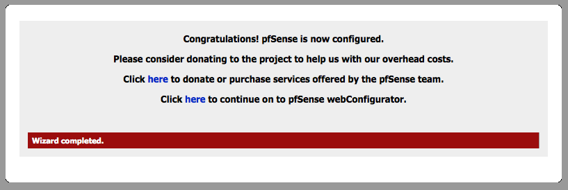
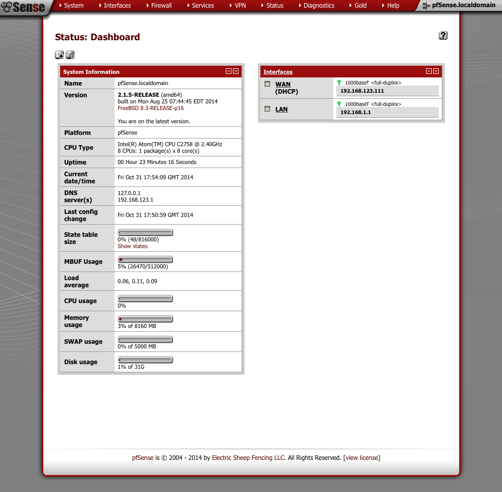
Click on ‘here’ to continue to the pfSense Webconfigurator where we will conduct the remaining configuration steps. You should now see the pfSense dashboard which should look something like this.
pfSense Configuration
We’ll set up some general configuration options first, using the menu bar at the top of the page navigate through to
System > Advanced > Admin Access
Proceed down the page configuring the sections as outlined below.
Web Configurator
To increase security set the GUI access to be via HTTPS and chose a port other than 443, I use 445. One of the reasons for this is to ensure we can generate safe anti-lockout rules which will prevent us locking ourselves out of the GUI when we start creating firewall rules later.
- Protocol = HTTPS
- SSL certificate = webConfigurator default
- TCP Port = 445 (or your preference)
- Disable Web GUI autocomplete = [√]
Secure Shell
Enable SSH access to pfSense which we’ll make use of later. I use a custom port of 422.
Secure Shell
- Enable Secure Shell = [√]
- SSH port = 422
- Click Save.
At this point you will be logged out and back in again on the new secure port, i.e https://192.168.1.1:445. When you log back in the banner will flash to advise pfSense has started creating SSH keys. Click on the warning and ‘Acknowledge All Notices’ to stop the flashing.

Navigate to System > Advanced > Firewall/NAT
Firewall Advanced
- Firewall Optimisation options = conservative
- Firewall Maximum States = 5000000
- Firewall maximum tables = 10000
- Firewall maximum table entries = 10000000
- Click Save.
Note: These numbers are set high enough to facilitate enabling some packet filtering software later. If you are running on a machine with very little RAM you may want to be adjust these numbers down accordingly.
Bogon Networks
- Update Frequency = Weekly
- Click Save
Navigate to System > Advanced > Networking
Network Interfaces
- Enable device polling = [ ]
- Disable hardware checksum offload = [ ]
- Disable hardware TCP segmentation offload = [√]
- Disable hardware large receive offload = [√]
- Click Save
Navigate to System > Advanced > Miscellaneous
Power Savings
- Use PowerD [√]
- on AC = HiAdaptive
- on Battery = HiAdaptive
Cryptographic Hardware Acceleration
If you are using an Intel processor select the following.
- Cryptographic Hardware = AES-NI CPU based Acceleration
- Thermal Sensors = Intel Core CPU on-die thermal sensor
- Click Save
Navigate to System > General Setup
Please set your domain name to something sensible but avoid ‘local’ as that will cause problems later.
- Hostname = pfSense
- Domain = yourname.local.lan
We will use OpenDNS servers. OpenNIC are very a good alternative but they are country specific so you would have to look up the ones relevant to your location.
- 1st DNS Server: 208.67.222.222 & Gateway = none
- 2nd DNS Server: 208.67.220.220 & Gateway = none
- Allow DNS overridden by DHCP/PPP on WAN = [ ]
- Do not use DNS forwarder for firewall = [ ]
- Timezone = set to your local timezone
- NTP Time Server =
0.pfsense.pool.ntp.org 1.pfsense.pool.ntp.org 2.pfsense.pool.ntp.org 3.pfsense.pool.ntp.org - Click Save
Setup LAN interface
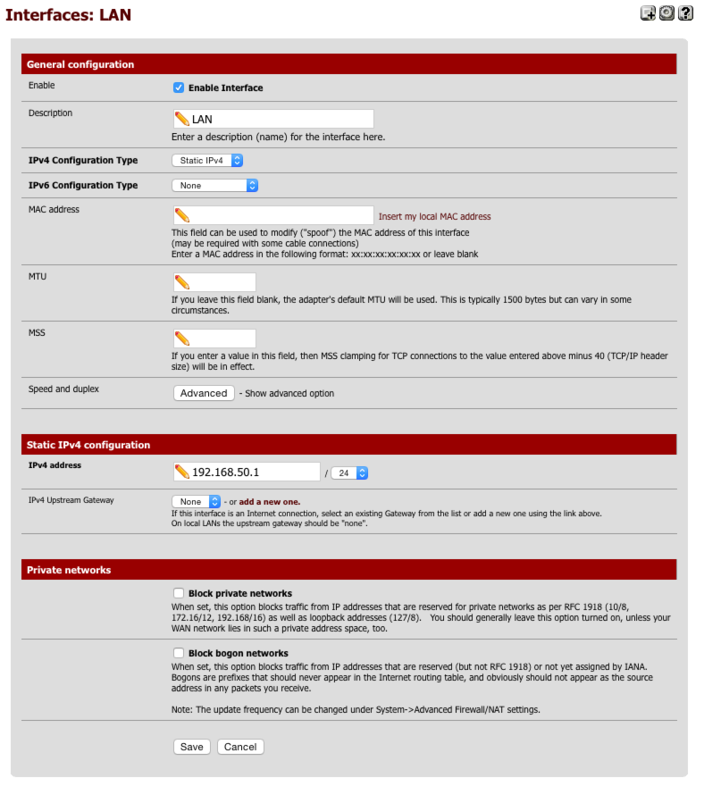
Navigate to Interfaces > LAN
General Configuration
- Enabled = [√]
- Description = LAN
- IPv4 = Static IPv4
- IPv6 = None
- Mac address = None
- MTU = None
- MSS = None
- Speed & duplex = standard
Static IPv4 configuration
- IPv4 Address = 192.168.50.1/24
- IPv4 Upstream gateway = None
Private Networks
- Block private networks = [ ]
- Block bogon networks = [ ]
Click Save & Apply changes.
Here’s a screen capture of my LAN interface page for reference.
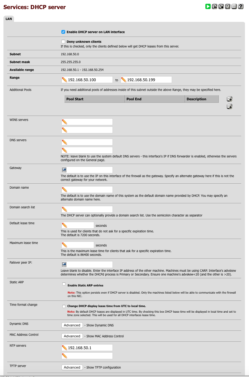
Configure LAN DHCP
Navigate to Services > DHCP Server and select LAN tab
- Enable = [√]
- Range 192.168.50.100 - 192.168.50.199
- DNS servers = leave blank as DHCP will serve interface address to clients to use DNS Forwarder
- NTP = 192.168.50.1
Here’s a screen capture of my LAN DHCP page for reference.
Setup VPN_LAN Interface
Navigate to Interfaces > Assign
Select an available OPTx interface to use for our VPN_LAN and set up the interface as follows.
General Configuration
- Enabled = [√]
- Name = VPN_LAN
- IPv4 = Static
- IPv6 = None
- Mac = empty
- MTU=blank
- MSS = empty
- Speed & duplex = standard
- Static IPv4 Address = 192.168.70.1/24
- IPv4 Upstream gateway = none
- Block private networks = [ ]
- Block bogon networks = [ ]
- Save & Apply
Configure VPN_LAN DHCP
Navigate to Services > DHCP Server
Select VPN_LAN tab
- Enable = [√]
- Range 192.168.70.100 - 192.168.70.199
- DNS servers = blank (Our DNS Forwarder will handle)
- NTP = 192.168.70.1
- Save & Apply
Install AirVPN certificates
Now we’ll download our AirVPN certificates from airvpn.org. Log into your account and navigate to Client Area > Config Generator and enter the following settings.
- Operating System = Router
- Servers = United Kingdom (or your preferred location)
- Connection Modes = Advanced [√]
- Direct, protocol UDP, port 443
- Advanced
- Separate keys/certs from .ovpn file [√]
Scroll down to the bottom of the page and agree to terms of service.
Click on [Generate] and download the resulting files to your desktop. We’ll use these various files to configure the OpenVPN client in pfSense in the next step.
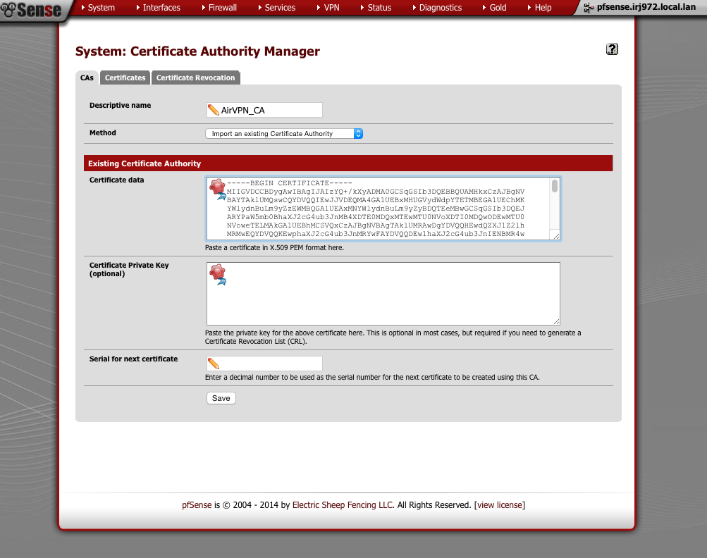
Back in pfSense’s GUI, we’ll create the Certificate Authority first.
Navigate to System > Cert Manager > CAs
- Click ‘+’
- Method = Import existing cert
- Descriptive Name = AirVPN_CA
- Method = Import an existing Certificate Authority
- Certificate data = Paste contents of ca.crt file in here
- Click Save
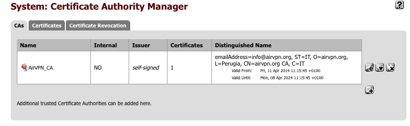
This is what the certificate authority should look like once you’ve added it
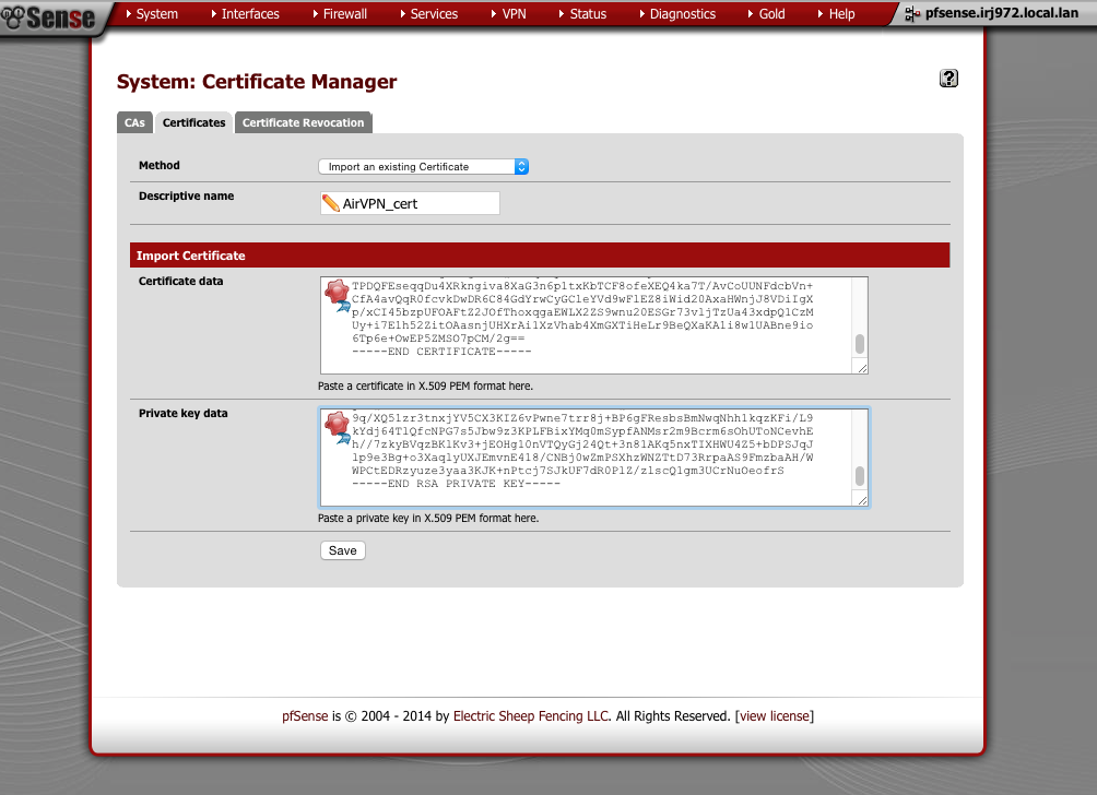
And now we’ll add the certificate.
Navigate to System > Cert Manager > Certificates
- Click ‘+’
- Method = Import existing cert
- Descriptive Name = AirVPN_cert
- Certificate data = paste contents of user.crt here
- Private key data = paste contents of user.key here
- Click Save
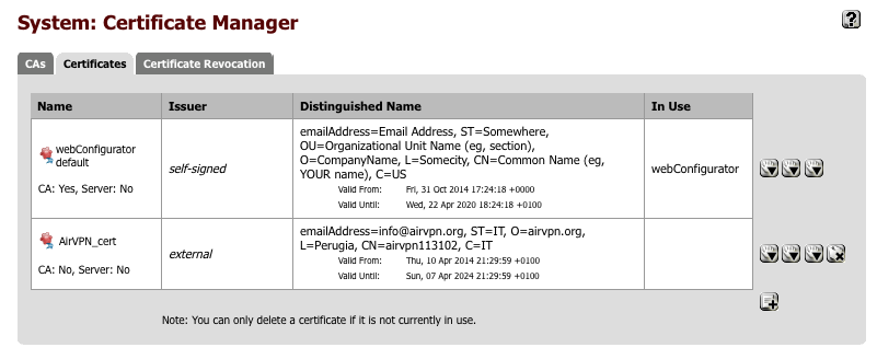
This is what the certificate should look like once you’ve added it
Create VPN connection
We’ll now configure the VPN connection itself.
Navigate to VPN > OpenVPN > Client
General Information
- Click ‘+’
- Server Mode = Peer to Peer (SSL / TLS)
- Protocol = UDP
- Device mode = tun
- Interface = WAN
- Server host = gb.vpn.airdns.org (or yours from the Air VPN configuration file you downloaded)
- Server port = 443 (from Air VPN configuration file)
- Proxy host = empty
- Proxy port = empty
- Proxy authentication extra options = none
- Server host name resolution = [√] Infinitely resolve server
- Description = AirVPN client
User Authentication Settings
- All blank
Cryptographic settings
- Enable authentication of TLS packets = [√]
- Automatically generate shared TLS authentication key = [ ]
- Shared key = Paste contents of the ta.key file you downloaded
- Peer certificate authority = AirVPN_CA
- Client certificate = AirVPN_cert
- Encryption algorithm = AES-256-CBC
- Hardware crypto = Intel RDRAND (assuming you have an Intel processor)
Tunnel Settings
- All blank
Advanced Configuration
Paste the following into the advanced box
remote-cert-tls server;tls-cipher TLS-DHE-RSA-WITH-AES-256-CBC-SHA;tls-exit;keysize 256;auth SHA1;key-method 2;key-direction 1;comp-lzo no;verb 4;explicit-exit-notify 5;bcast-buffers 4096;fast-io;mlock;topology net30;keepalive 5 30;route-nopull;prng sha512 64;
- Click Save
Assign OpenVPN interface
Navigate to Interfaces > Assign
- Click ‘+’ at the bottom right which will add a new OPTx interface.
- Set Network port for the new Interface = ovpnc1()
- Click on the new interface name, OPTx.
- Enable Interface = [√]
- Description = VPN_WAN
- IPv4 Configuration Type = None
- IPv6 Configuration Type = None
- Mac Address = blank
- MTU = blank
- MSS = blank
- Block private networks = [ ]
- Block bogon networks = [ ]
- Click Save & Apply changes
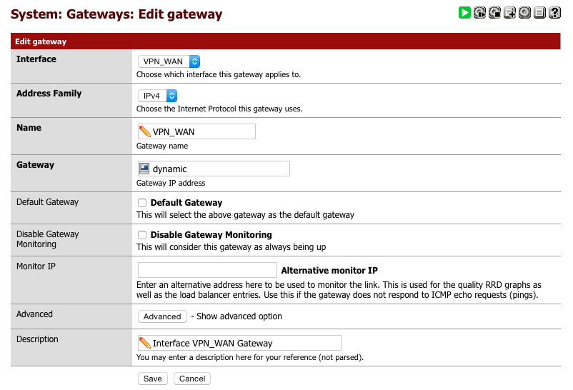
Setup AirVPN Gateway
Navigate to System > Routing.
Its important make sure you click on the ‘+’ alongside the VPN_WAN_VPNV4 line.
- Interface = VPN_WAN
- Address family = IPv4
- Name = VPN_WAN
- Gateway = dynamic
- Default Gateway = [ ]
- Disable gateway monitoring = [ ]
- Monitor IP = 10.4.0.1
- Advanced = unchanged
- Description = Interface VPN_WAN Gateway
- Click Save
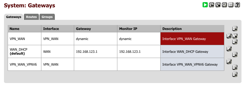
After configuring the gateway, the summary page should look like this.
To reduce the chance of any leaks in the event the VPN goes down for any reason.
Navigate to System > Advanced > Miscellaneous
- State Killing on Gateway Failure = [_]
- Skip rules when gateway is down = [√]
- Click Save
Set DNS Forwarder
The complexity and operational requirements of my network require my DNS forwarder to also support local name lookups for servers but also for device auto configuration via WPAD.
There are several ways to handle DNS lookups securely without introducing leaks and I believe this is a good compromise between functionality and security. I’ve spent some time verifying there are no leaks with this setup. With v2.2 of pfSense we will be able to migrate to a better DNS Resolver which will provide additional functionality that will help improve this area further. I’ll update this guide once 2.2 has been released.
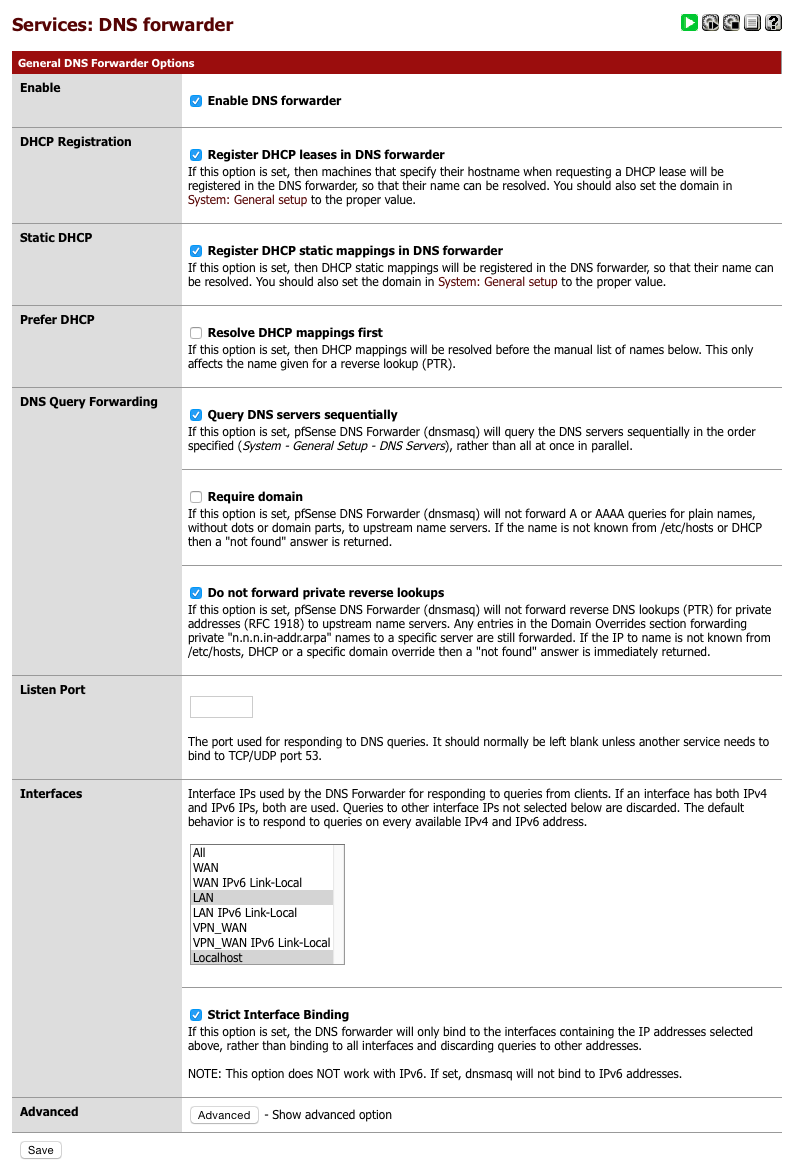
Navigate to Services > DNS Forwarder
- Enable Forwarder = [√]
- Register DHCP leases in DNS Forwarder = [√]
- Register DHCP static leases in DNS Forwarder = [√]
- Resolve DHCP mappings first = [ ]
- Query DNS servers sequentially = [√]
- Require Domain = [ ]
- Do not forward private lookups = [√]
- Interfaces = LAN, VPN_LAN & Localhost
- Strict interface binding = [√]
- Click Save
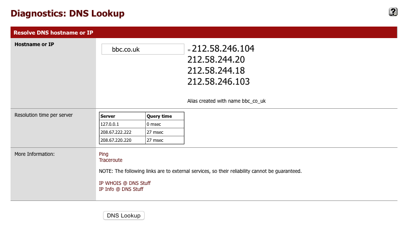
Its worth verifying that basic DNS lookups work before we complicate it by introducing the VPN DNS servers.
Navigate to Diagnostics > DNS Lookup
- Enter an address to test lookups with.
- Click DNS Lookup
You should see a series of IP addresses returned and times taken for the various servers to respond.
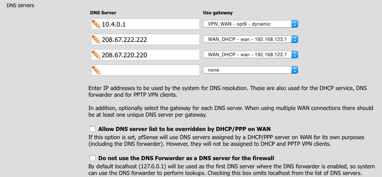
Now we’ll add in the AirVPN DNS server. Its important this is placed at the top of the following list and that sequential checking was applied in the DNS Forwarder to prevent DNS leaks.
Navigate to General > System
Set DNS servers as follows. Note the 10.4.0.1 address is via the VPN_WAN gateway.
- 10.4.0.1 & VPN_WAN
- 208.67.222.222 & WAN_DHCP
- 208.67.220.220 & WAN_DHCP
Your setup should look something like the image below.
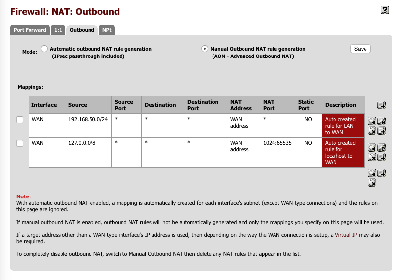
Set up outgoing NAT for LAN & Localhost
Navigate to Firewall > NAT > Outbound
- Select Manual outbound NAT rule generation
- Click Save
A number of rules will be created automatically, you can delete any with ‘500’ in the Destination Port column as we won’t need these.
Click the ‘e’ next to 127.0.0.0 / 8 line.
- Do not NAT = [ ]
- Interface = WAN
- Protocol = any
- Source
- Type = Network
- Address = 127.0.0.0 / 8
- Source port: Blank - Destination = Blank
- Type = Any
- Address = Blank
- Destination Port: Blank - Translation
- Address = Interface Address
- Port = 1024:65535
- Description = Localhost to WAN - Click Save
Click the ‘e’ next to 192.168.50.0/24 line.
- Do not NAT = [ ]
- Interface = WAN
- Protocol = any
- Source
- Type = Network
- Address = 192.168.50.0 / 24
- Source port: Blank - Destination = Blank
- Type = Any
- Address = Blank
- Destination Port: Blank - Translation
- Address = Interface Address
- Port = Blank
- Description = LAN to WAN - Click Save
Click the ‘e’ next to 192.168.70.0/24 line.
- Do not NAT = [ ]
- Interface = WAN
- Protocol = any
- Source
- Type = Network
- Address = 192.168.70.0 / 24
- Source port: Blank - Destination = Blank
- Type = Any
- Address = Blank
- Destination Port: Blank - Translation
- Address = Interface Address
- Port = Blank
- Description = VPN_LAN to WAN - Click Save
When you are complete, the NAT: Outbound page should look like this.
Create Aliases for firewall rules
We are going to create a few aliases which we will use in the creation of the firewall rules. These simplify the job of making changes in future especially as we add more interfaces and functionality to our network.
Navigate to Firewall > Aliases > IP
First we will create an alias to define the internal subnets, at this stage this only consists of two but it will expand as we grow our network.
- Click ‘+’
- Name = LOCAL_SUBNETS
- Description = local.lan subnets
- Type = Networks
- 192.168.50.0 / 24 “LAN subnet”
- 192.168.70.0 / 24 “VPN subnet” - Click Save
Navigate to Firewall > Aliases > Ports
We will create a list to define which ports administration traffic flows on, we’ll green light these with a dedicated rule on key interfaces to ensure we don’t lock ourselves out when configuring the firewall. Make sure these ports match the ones you set earlier on the Advanced > Admin Access page.
- Click ‘+’
- Name = ANTILOCKOUT
- Description = Admin ports
- Type = Ports
- Ports(s) =
- 445 : Web GUI
- 422 : SSH - Click Save
Navigate to Firewall > Aliases > Ports
We will create a list of ports to define which ports can reach the internet. You should amend this as per your networks requirements.
- Click ‘+’
- Name = ALLOWED_OUT_PORTS_WAN
- Description = Open WAN ports
- Type = Ports
- Ports(s) =
- 22 : SSH
- 80 : HTTP
- 443 : HTTPS
- 1024:65535 : Unprivileged ports
- 587 : SMTPs
- 993 : IMAPs
- 5222 : XMPP
- 8080 : HTTP Alt
- 465 : SMTPs - Click Save
Setup Firewall Rules
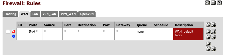
First we’ll set up the WAN interface. With no rules, any present traffic is still blocked, it just isn’t logged. We’ll add a catch all rule that prevents and crucially logs inbound traffic which wasn’t initiated by an internal device so we know whats trying to gain access.
WAN rules
Navigate to Firewall > Rules > WAN
- Click ‘+’
- Action = Block
- Interface = WAN
- TCP/IP Version = IPv4
- Protocol = Any
- Source = Any
- Destination = Any
- Log = [√]
- Description = WAN: default block
- Click [Save]
Your WAN interface should look this this when done.
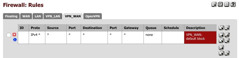
VPN_WAN rules
Now we’ll create a similar block rule on the VPN_WAN interface.
Navigate to Firewall > Rules > VPN_WAN
- Click ‘+’
- Action = Block
- Interface = VPN_WAN
- TCP/IP Version = IPv4
- Protocol = Any
- Source = Any
- Destination = Any
- Log = [√]
- Description = VPN_WAN: default block
- Click [Save]
Your VPN_WAN interface should look this this when done.
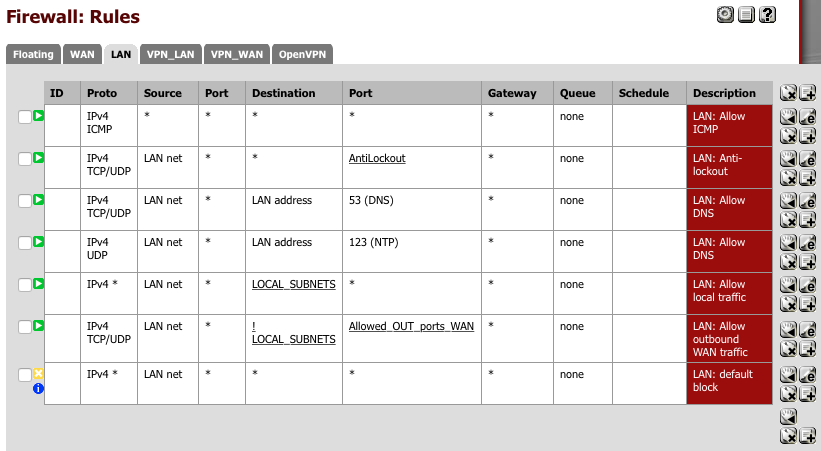
LAN rules
Now we will create the rules for our LAN interface. The LAN rulesets are more complicated as we need to ensure traffic can flow between internal subnets and the external internet on specific ports.
Navigate to Firewall > Rules > LAN and create the following rules.
This rule allow Pings to be leave the interface which are useful for network debugging.
- Click ‘+’
- Action = Pass
- Interface = Any
- TCP/IP Version = IPv4
- Protocol = ICMP
- Source = Any
- Destination = Any
- Log = [ ]
- Description = LAN: Pass ICMP
- Click [Save]
This rule ensures traffic targeted on any of our Admin ports is allowed. This is our anti-lockout rule.
- Click ‘+’
- Action = Pass
- Interface = LAN net
- TCP/IP Version = IPv4
- Protocol = TCP/UDP
- Source = LAN net
- Destination = Any
- Port = ANTILOCKOUT
- Log = [ ]
- Description = LAN: Pass Admin
- Click [Save]
Our DNS rule only allows DNS lookups on the local interface, i.e our DNS Forwarder. This prevents any DNS hijacking on attached clients from redirecting DNS towards hostile resources. DNS primarily works over UDP but does have a fallback state to TCP which I’ve allowed as well.
- Click ‘+’
- Action = Pass
- Interface = LAN net
- TCP/IP Version = IPv4
- Protocol = TCP/UDP
- Source = LAN net
- Destination = LAN address
- Port = 53 (DNS)
- Log = [ ]
- Description = LAN: Pass DNS
- Click [Save]
Only allow Network Time Protocol syncing on the local interface which prevents any traceable lookups from alternative sources. pfSense itself uses 0.pfsense.pool.ntp.org for its lookups which is configured on the System > General page. Its a good idea to keep everything on your internal networks synced to the same time source.
- Click ‘+’
- Action = Pass
- Interface = LAN net
- TCP/IP Version = IPv4
- Protocol = UDP
- Source = LAN net
- Destination = LAN address
- Port = 123 (NTP)
- Log = [ ]
- Description = LAN: Pass NTP
- Click [Save]
Allow all traffic to our other local subnets. You can lock this down to a limited number of ports if preferred using an alias to define ALLOWED_OUT_PORTS_LAN for example.
- Click ‘+’
- Action = Pass
- Interface = LAN net
- TCP/IP Version = IPv4
- Protocol = Any
- Source = LAN net
- Destination = Single host or alias
- Address = LOCAL_SUBNETS
- Port = Any
- Log = [ ]
- Description = LAN: Pass subnet
- Click [Save]
Allow traffic to the internet, (which is )defined as anywhere NOT a local subnet). We close this access down to the list of ports within the AALLOWED_OUT_PORTS_WAN alias we created.
- Click ‘+’
- Action = Pass
- Interface = LAN net
- TCP/IP Version = IPv4
- Protocol = TCP/UDP
- Source = LAN net
- Destination
- Not = [√]
- Single host or alias
- Address = LOCAL_SUBNETS
- Port = Allowed_out_ports_WAN
- Log = [ ]
- Description = LAN: Pass WAN Outbound
- Click [Save]
and finally a rule to block and importantly log any traffic which hasn’t been handled by one of the above rules.
- Click ‘+’
- Action = Reject
- Interface = LAN net
- TCP/IP Version = IPv4
- Protocol = Any
- Source = LAN net
- Destination = Any
- Port = Any
- Log = [√]
- Description = LAN: Default block
-
Click [Save]
- Click [Apply].
Your LAN rules should look something like this now.
As we have created our own Anti-lockout rule above, you can disable the system generated anti-lockout rule in System > Advanced > Anti-lockout.
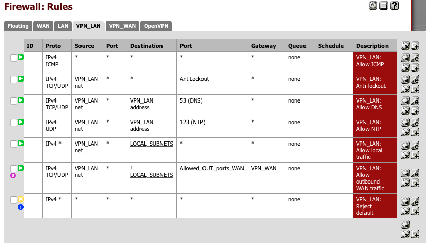
VPN_LAN rules
Now we will create a set of rules for the VPN_LAN interface too. These are largely the same but with a changes to allow for the use of our VPN gateway for external traffic.
Navigate to Firewall > Rules > VPN_LAN and create the following rules.
This rule allow Pings to be generated which are useful for network debugging.
- Click ‘+’
- Action = Pass
- Interface = Any
- TCP/IP Version = IPv4
- Protocol = ICMP
- Source = Any
- Destination = Any
- Log = [ ]
- Description = VPN_LAN: Pass ICMP
- Click [Save]
This rule ensures traffic targeted on either of our Admin ports is allowed.
- Click ‘+’
- Action = Pass
- Interface = VPN_LAN net
- TCP/IP Version = IPv4
- Protocol = TCP/UDP
- Source = VPN_LAN net
- Destination = Any
- Port = ANTILOCKOUT
- Log = [ ]
- Description = VPN_LAN: Pass Admin
- Click [Save]
Our DNS rule only allows DNS lookups on the local interface.
- Click ‘+’
- Action = Pass
- Interface = VPN_LAN net
- TCP/IP Version = IPv4
- Protocol = TCP/UDP
- Source = VPN_LAN net
- Destination = VPN_LAN address
- Port = 53 (DNS)
- Log = [ ]
- Description = VPN_LAN: Pass DNS
- Click [Save]
Only allow Network Time Protocol syncing on the local interface.
- Click ‘+’
- Action = Pass
- Interface = VPN_LAN net
- TCP/IP Version = IPv4
- Protocol = UDP
- Source = VPN_LAN net
- Destination = VPN_LAN address
- Port = 123 (NTP)
- Log = [ ]
- Description = VPN_LAN: Pass NTP
- Click [Save]
Allow traffic to our other local subnets.
- Click ‘+’
- Action = Pass
- Interface = VPN_LAN net
- TCP/IP Version = IPv4
- Protocol = Any
- Source = VPN_LAN net
- Destination = Single host or alias
- Address = LOCAL_SUBNETS
- Port = Any
- Log = [ ]
- Description = VPN_LAN: Pass subnet
- Click [Save]
Allow traffic to leave for the internet which is defined as anywhere NOT a local subnet. Note the different gateway address for this.
- Click ‘+’
- Action = Pass
- Interface = VPN_LAN net
- TCP/IP Version = IPv4
- Protocol = TCP/UDP
- Source = VPN_LAN net
- Destination
- Not = [√]
- Single host or alias
- Address = LOCAL_SUBNETS
- Port = Allowed_out_ports_WAN
- Log = [ ]
- Description = VPN_LAN: Pass WAN Outbound
- Important: Advanced features, gateway = VPN_WAN
- Click [Save]
and finally a rule to block and log any traffic which hasn’t been handled by one of the above rules.
- Click ‘+’
- Action = Reject
- Interface = LAN net
- TCP/IP Version = IPv4
- Protocol = Any
- Source = LAN net
- Destination = Any
- Port = Any
- Log = [√]
- Description = VPN_LAN: Default block
-
Click [Save]
- Click [Apply].
At this stage it would be worthwhile rebooting your router. When you log back in to the dashboard you should hopefully see the interfaces panel displaying four active interfaces with green arrows.
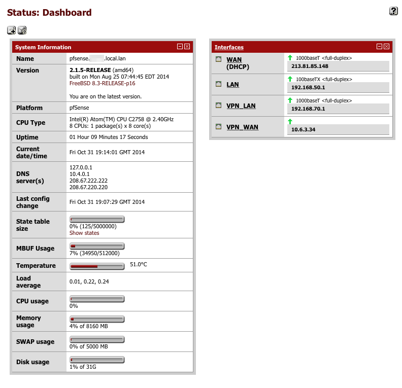
Dashboard
Its worth adding a few additional control panels to the dashboard to monitor the status and health of your system.
Click the ‘+’ in the top left corner and add the following.
- Gateways
- Firewall Logs
- NTP Status
- OpenVPN
- Services Status
- System Information
- Thermal Sensors
- Traffic Graphs
A few have local widget control options which you can access by clicking the spanner icon, remember to click [Save] when you have configured them how you want them.
Testing and verifying functionality
You should now have two LAN inputs, one providing access to a clear net connection, and one providing access via AirVPNs network. I have separate Apple Airport devices connected to these which provide the ability to jump from clearnet to VPN connections easily from laptops or tablets.
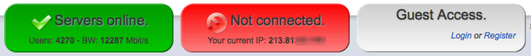
To verify both connections are working correctly, go to airvpn.org. At the bottom of the page you’ll see a status which reflects if you are connected to their network or not. Check it reflects which LAN port you are connected to.
When connecting via your VPN you should see the following:

and when connecting via your clearnet you should see the following:
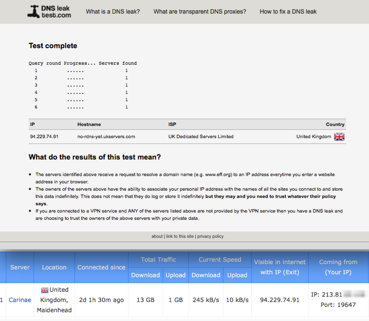
Verify no DNS Leaks
Its worth verifying your system isn’t leaking DNS lookups by visiting DNSLeakTest.com
Having run a test you should not observe your real IP address displayed, if you do you have a configuration issue you should resolve it.
Verify Local DNS lookups
One of the reason for configuring the DNS Forwarder as I did is to allow internal DNS lookups. To verify this is working open a command prompt and perform a nslookup on some internal devices. Here is a screenshot of my tests on both an internal (pfSense router) and external (airvpn.org) address.
$ nslookup pfsense
Server:     192.168.71.1
Address:    192.168.71.1#53

Name:   pfsense.home.local.lan
Address: 192.168.50.1

$ nslookup airvpn.org
Server:     192.168.71.1
Address:    192.168.71.1#53

Non-authoritative answer:
Name:   airvpn.org
Address: 95.211.138.143
or using dig
$ dig pfsense

; <<>> DiG 9.8.3-P1 <<>> pfsense
;; global options: +cmd
;; Got answer:
;; ->>HEADER<<- opcode: QUERY, status: NOERROR, id: 16423
;; flags: qr aa rd ra; QUERY: 1, ANSWER: 1, AUTHORITY: 0, ADDITIONAL: 0

;; QUESTION SECTION:
;pfsense.           IN  A

;; ANSWER SECTION:
pfsense.        3600    IN  A   192.168.50.1

;; Query time: 4 msec
;; SERVER: 192.168.71.1#53(192.168.71.1)
;; WHEN: Sun Jan 24 10:30:25 2016
;; MSG SIZE  rcvd: 41

$ dig airvpn.org

; <<>> DiG 9.8.3-P1 <<>> airvpn.org
;; global options: +cmd
;; Got answer:
;; ->>HEADER<<- opcode: QUERY, status: NOERROR, id: 23854
;; flags: qr rd ra; QUERY: 1, ANSWER: 1, AUTHORITY: 6, ADDITIONAL: 12

;; QUESTION SECTION:
;airvpn.org.            IN  A

;; ANSWER SECTION:
airvpn.org.     215 IN  A   95.211.138.143

;; AUTHORITY SECTION:
org.            79522   IN  NS  a0.org.afilias-nst.info.
org.            79522   IN  NS  d0.org.afilias-nst.org.
org.            79522   IN  NS  c0.org.afilias-nst.info.
org.            79522   IN  NS  b0.org.afilias-nst.org.
org.            79522   IN  NS  a2.org.afilias-nst.info.
org.            79522   IN  NS  b2.org.afilias-nst.org.

;; ADDITIONAL SECTION:
a0.org.afilias-nst.info. 153761 IN  A   199.19.56.1
a0.org.afilias-nst.info. 153761 IN  AAAA    2001:500:e::1
a2.org.afilias-nst.info. 63787  IN  A   199.249.112.1
a2.org.afilias-nst.info. 150267 IN  AAAA    2001:500:40::1
b0.org.afilias-nst.org. 63867   IN  A   199.19.54.1
b0.org.afilias-nst.org. 63867   IN  AAAA    2001:500:c::1
b2.org.afilias-nst.org. 63867   IN  A   199.249.120.1
b2.org.afilias-nst.org. 63867   IN  AAAA    2001:500:48::1
c0.org.afilias-nst.info. 71058  IN  A   199.19.53.1
c0.org.afilias-nst.info. 71058  IN  AAAA    2001:500:b::1
d0.org.afilias-nst.org. 63867   IN  A   199.19.57.1
d0.org.afilias-nst.org. 63867   IN  AAAA    2001:500:f::1

;; Query time: 3 msec
;; SERVER: 192.168.71.1#53(192.168.71.1)
;; WHEN: Sun Jan 24 10:30:32 2016
;; MSG SIZE  rcvd: 446
Performance
Here’s a Speedtest comparison of my speeds on a direct connection via Virgin and a connection via AirVPN.
Without AirVPN - Virgin media direct
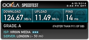
With AirVPN