pfSense 2.3 setup with AirVPN, DNS Resolver and VLANs
Last revised 5 April 2016.
NOTE: This pfSense 2.3 guide is now deprecated, please see the updated pfSense 2.4 guide here.
Introduction
My setup has changed pretty significantly from my original pfSense guide and I wanted to update it reflect some of those improvements.
The changes include:-
- Based on pfSense 2.3 which includes a new look and feel as well as other numerous updates and improvements.
- Increased security via improved firewall rule sets
- Replaced Apple Airport wifi access points with Ubiquiti Unifi enterprise wifi access points
- use of multiple VLANs to segregate traffic between the various networks rather than relying on multiple NICs.
- provision of a dedicated ‘guest’ network for visitors.
- replaced DNS Forwarder with the DNS Resolver.
- Provide Inbound access via OpenVPN for remote access to services
- Implemented pfBlockerNG to provide network wide advert and tracker scrubbing.
- Simultaneous multiple VPN WAN connections providing redundancy
- ISP speed increased to 150/150mbps up/down from 150/15.
I’m not going to set up all the above services in this base guide, my plan is to provide them as add-on steps for those who need them. This is a slightly more lengthy and complicated setup than the previous guide but I think the trade offs are worth it. I’ve added some further explanations along the way try and compensate for new users.
Requirements
My home and office has grown to require more than just the two local networks my previous guide afforded me. I now require the following isolated segments and primarily this drove my decision to move to a VLAN based setup.
Unencrypted ‘clearnet’
Used for general purpose surfing when an encrypted line isn’t a requirement.
Secure VPN
Primary LAN network where all traffic which exits is encrypted via OpenVPN and exits to the internet via an AirVPN end point disguising my location.
Guest network
Effectively this exposes my native unencrypted unsecured Verizon FIOS line complete with Verizons DNS servers. Used primarily by visitors who require internet access but also acts as a backup if AirVPN goes down for any reason. Also prevents access to all local resources such as file servers etc.
Management network
Used for native hardware access such as Unifi access points as well as interfaces intended to be utilised only by an admin user, for example, IPMI interfaces on headless servers.
Security cameras
Subnet which various security cameras are connected to. This line is heavily locked down to prevent anyone from attempting to gain access to my home network via compromising an external cable or hacking a camera.
DMZ
Used to provide a de-restricted zone for servers and other devices which need to be accessed remotely.
Still AirVPN?
I continue to use AirVPN as my primary VPN provider, downtime is a rare and performance on the whole is still excellent. There are a number of VPN providers on the market but the reasons why I originally went with AirVPN are primarily:
- Its operated by activists interested in defence of net neutrality, privacy and censorship.
- Ability to surf anonymously with no logging or monitoring
- Good security, OpenVPN based, 4096 bit RSA key-sizes & AES-262-CBC data channel
- Internal DNS with anti-ICE/ICANN censorship.
- Supports port forwarding / DDNS.
- High performance servers in multiple countries
- No traffic limits, no speed filtering
- Three simultaneous connections
- Accepts bitcoin
I found AirVPN speeds were best in class when I benchmarked a few of the other highly ranked providers previously. I’ve been with AirVPN for several years and have suffered downtime of less than an hour. If you haven’t got an Air VPN subscription, you can take out a subscription here.
Connection Specification
I upgraded to a 150/150 Verizon FIOS line which provides 150mbps upload and download simultaneously. With my current Intel C2758 hardware, the VPN encryption reduces performance by 10%. Lesser hardware may affect ultimate speeds more.
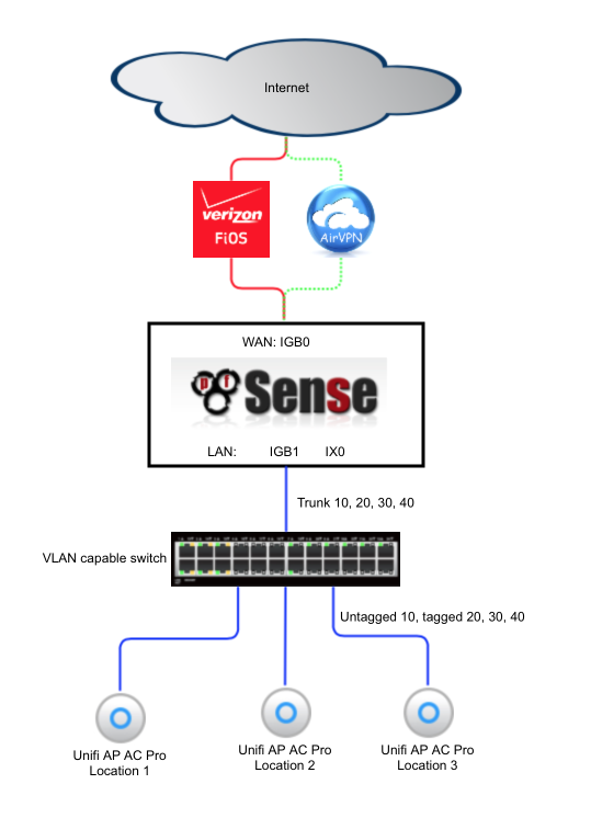
Topology
The following diagram illustrates the basic network topology of my network.
I had my Verizon ONT converted from the original coaxial cable to a Cat5 cable by Verizon which allowed me to connect my pfSense box directly to Verizons network without utilising their modem for anything other than enabling some TV set top box functionality. The cost of the conversion is free if you upgrade to a 150mbps service or above.
A managed switch is required to support reliable VLAN use and also provides additional ports to use multiple wifi access points to provide whole home coverage for wifi devices. I’ve listed a few cost effective managed switch options in the hardware section below.
Hardware selection
Although it is possible to build a pfSense router from pretty much any old hardware, I wanted to build something which was powerful enough to handle VPN encryption on a 100mbps+ connection with minimal latency and headroom to spare to run additional security and packet filtering packages like Snort or Suricata. I also plan on this router being in production use for a number of years so wanted to ensure it was able to manage future requirements as my Internet connection bandwidth increases.
I’m currently using the following hardware in my pfSsense box.
- Motherboard: Supermicro A1SRM
- Processor: Intel Atom processor C2758 2.4Ghz, 8-core, 20W
- RAM: 16GB (2x8GB) DDR3 1600Mhz
- System Disk: Supermicro SATA-DOM 16GB
- Case & PSU: Supermicro CSE-505-203B
- Additional NIC: Intel X520
A managed switch is required to provide support for the VLANs, the following are suitable options and many are available on Ebay cheaply. Look for 802.1Q support which is the ability apply VLAN tags to traffic.
MikroTik RB260GS available for around $40. Accompanying VLAN Config guide here
NETGEAR ProSAFE GS108E available for around $50. Accompanying VLAN Config guide here
Cisco sg300-10 available for around $130.
If you expect to have multiple heavily used subnets you may wish to consider looking for a switch which offers a 10gbe uplink port as this facilitates a larger trunk connection to the pfsense router and corresponding higher throughput.
You don’t need to use multiple Unifi access points, each one provides all the VLANs we need however depending on the size of the property you are trying to provide wifi access to, additional APs may be required.
Install pfSense
Download and create bootable pfSense USB based installer
As of the time of writing, pfSense 2.3 is still in beta nearing RC status. You will need to download 2.3 from the Daily Snapshots section here.
I downloaded and used the 64bit AMD64 Live CD/Installer ISO which I burned to a 2GB+ USB stick with Win32 disk Imager.
Set BIOS settings to enable pfSense to install
- Ensure AHCI is OFF and ATA mode is selected
- Disbale any unused features
Install
Insert the USB stick in an available USB port and boot the system from the USB stick. You may need the boot options (F11) or use the Boot menu in the BIOS to set appropriately.
After a short wait you will see a prompt to Press 'I' to launch the installer which will begin installing pfSense to your local hard disk.

Configure Console
The first screen you will be presented with gives you the chance to modify the console settings. Select ‘Accept these settings’.

Select Task
If you are comfortable installing to the first hard disk in your system, go ahead and select Easy Install. Custom Install is beyond the scope of this guide but will enable you to select a specific disk and customise the initialisation options.

Verify you are sure and the installer will go ahead and format your primary hard disk and copy the pfSense files across to it.
Install Kernel
When prompted to install a kernel, select Standard Kernel.

Reboot
After a short wait, you will be presented with an option to reboot. Select Reboot and when the system reaches an appropriate state, remove the USB boot disk and boot from the system disk.

Initial Configuration
Your pfSense machine should now proceed to boot from the fresh install. After a short while of you should see a option page which looks something like this.
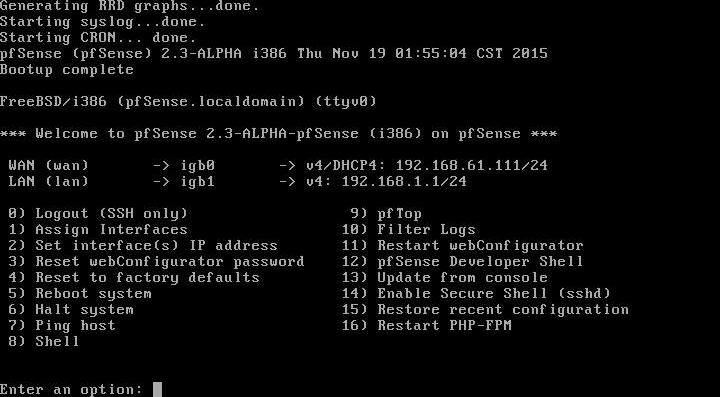
By default the installer configures the first NIC as the WAN port obtaining an address via DHCP and the second NIC as your LAN interface at 192.168.1.1. There’s a DHCP server running on this interface so if you connect your PC to this port, you should receive an address which will allow us to get to the GUI to continue our configuration.
First login
Open a browser and enter http://192.168.1.1 into the address bar, you should be presented with a login screen as shown below.
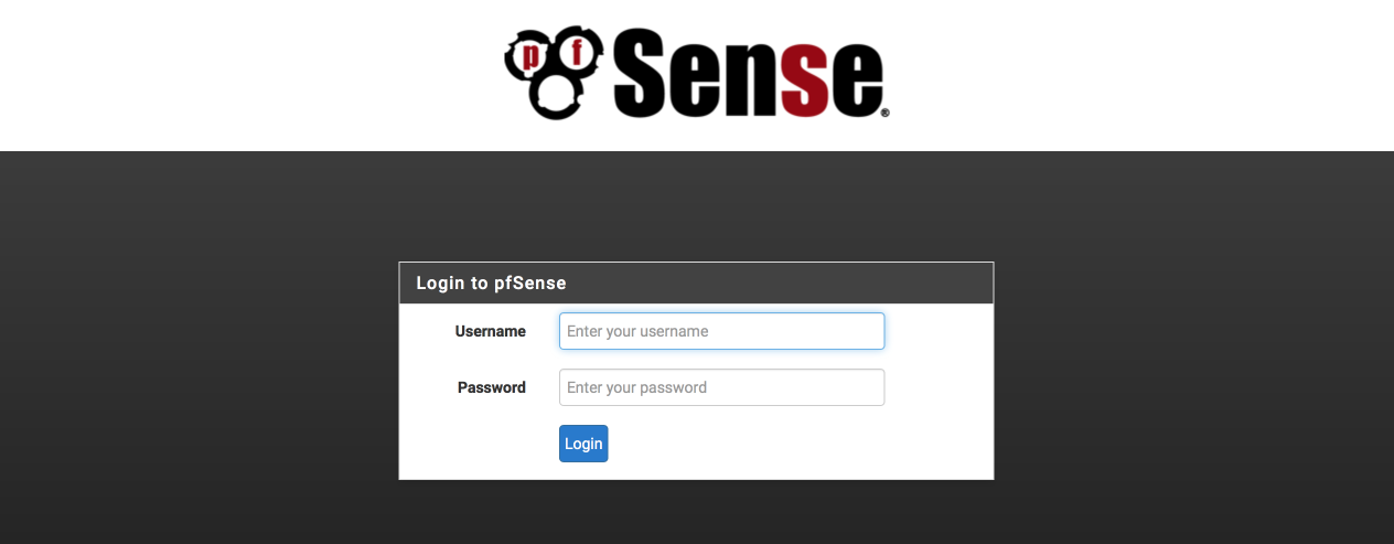
Enter the username as ‘admin’ and the password as ‘pfsense’ to login.
pfSense wizard setup
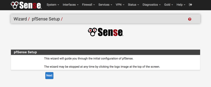
The Wizard will guide you through the initial configuration steps.
Select next to begin.
Bling your pfsense with pfSense gold
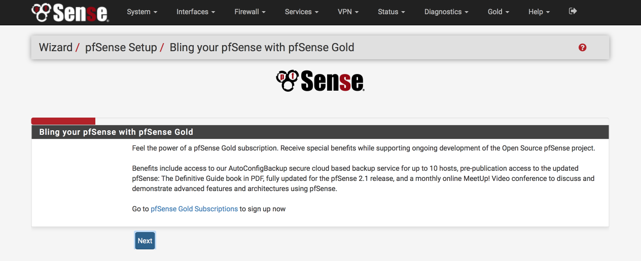
You’ll be offered the chance to purchase a pfSense gold subscription which offers benefits including autobackup, regular video conferences and probably more importantly the definitive guide book which is a great resource to have handy.
Select ‘next’ to continue.
General Information
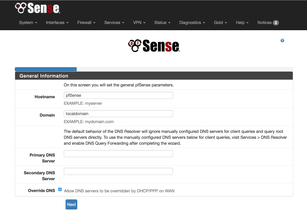
Configure this screen as specified below. We’ll use the OpenDNS servers for initial DNS resolution.
- Hostname: pfSense
- Domain: local.lan
- Primary DNS server: 208.67.222.222
- Secondary DNS server: 208.67.220.220
- Allow DNS to be over ridden on WAN: unticked
- Select Next
Configure NTP
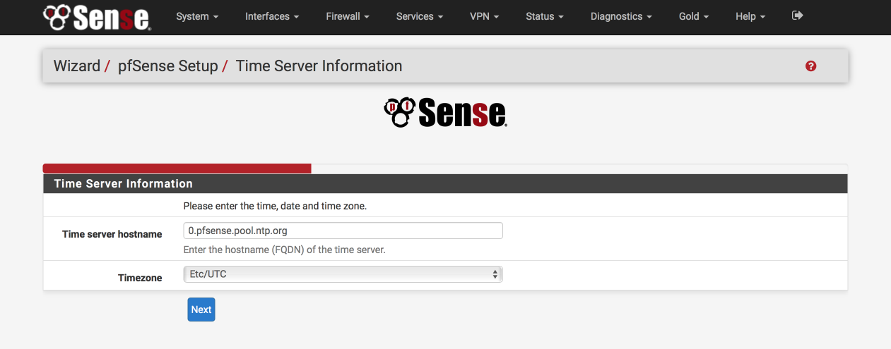
The default Time server hostname is usually correctly specified but make sure to set the Timezone to your own specific location.
- Time server hostname: 0.pfsense.pool.ntp.org
- Timezone: your local timezone
- Select Next
Configure WAN Interface
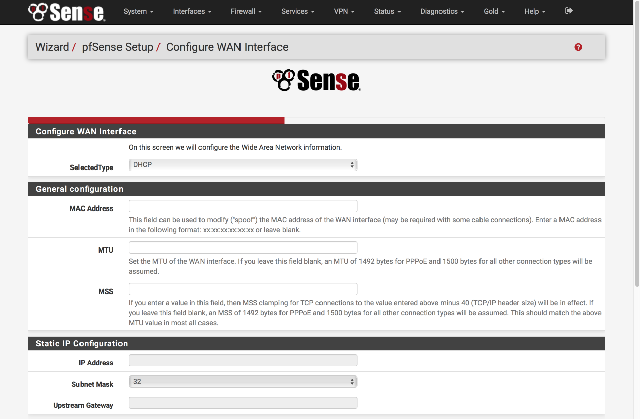
Configure this page as follows. Most of these options will remain as default, i.e empty.
Configure WAN Interface
- Selected Type: DHCP
General Configuration
- MAC Address: Empty
- MTU: Empty
- MSS: Empty
Staic IP Address
- IP Address: Empty
- Subnet Mask: 32
- Upstream Gateway: Empty
DHCP client configuration
- DHCP hostname: Empty
PPPoE configuration
- PPoE username: Empty
- PPPoE Password: Empty
- Show PPPoE password: Empty
- PPoE service name: Empty
- PPPoE dial on demand: unticked
- PPPoE idle timeout: Empty
PPTP configuration
- PPTP username: Empty
- PPTP password: Empty
- Show PPTP password: Empty
- PPTP local IP address: Empty
- PPTP local subnet: 32
- PPTP remote IP address: Empty
- PPTP dial on demand: unticked
- PPTP idle timeout: Empty
RFC1918 networks
- Block RFC1918 Private networks: [√]
Block BOGON networks
- Block bogon netwoks: [√]
Select next to continue.
Configure LAN Interface
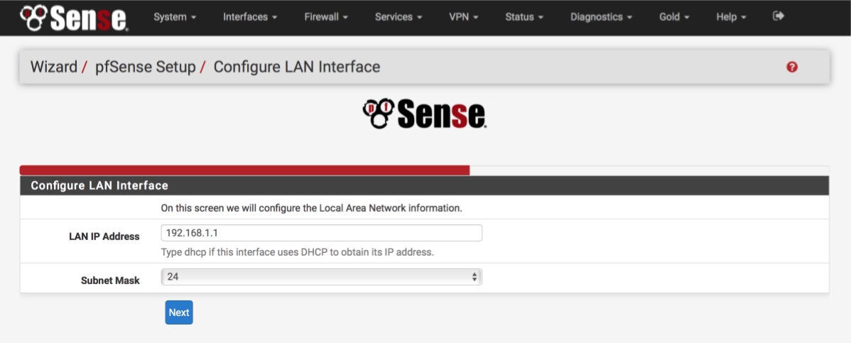
You can give your LAN interface a specific address here if needed. Leave it as 192.168.1.1 for now.
- LAN IP address: 192.168.1.1
- Subnet mask: 24
Select Next to continue.
Set Admin WebGUI Password
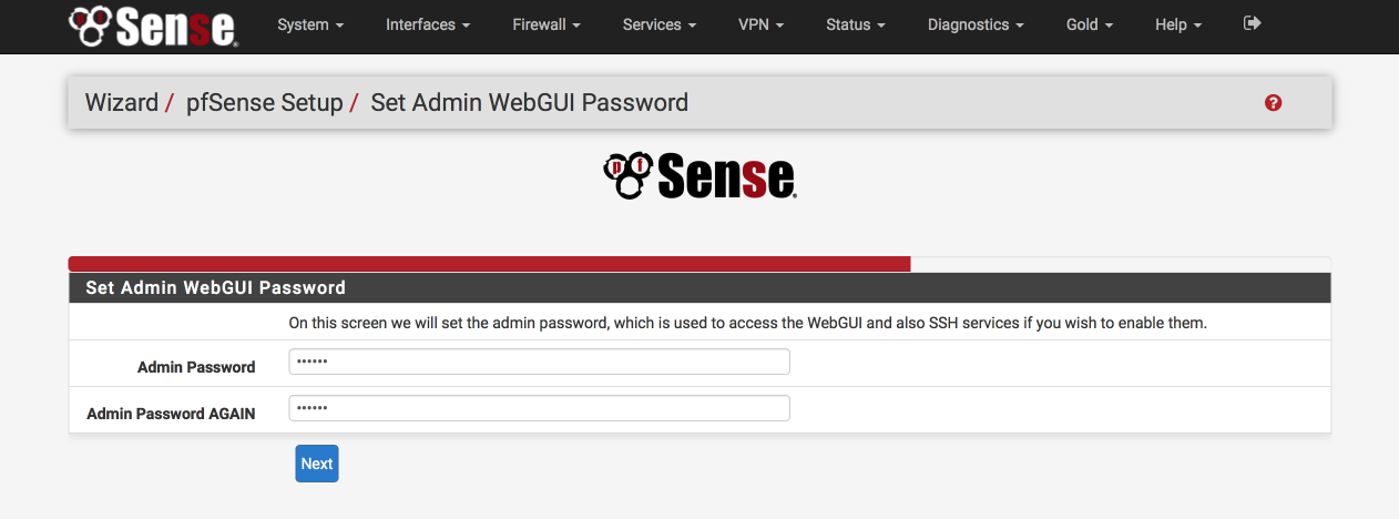
Select a srong password to protect unauthorised access to the web interface.
- Admin Password: a strong password
- Admin password again: a strong password again
Select Next to continue.
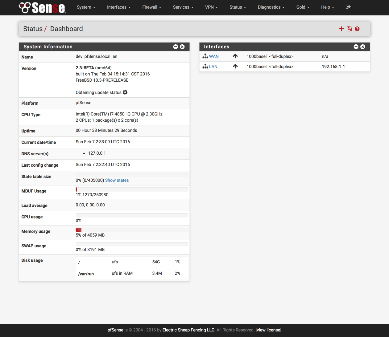
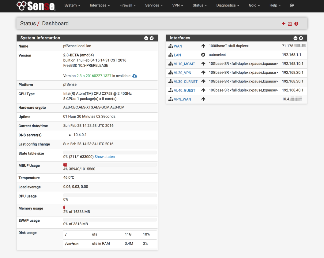
Enter the dashboard…
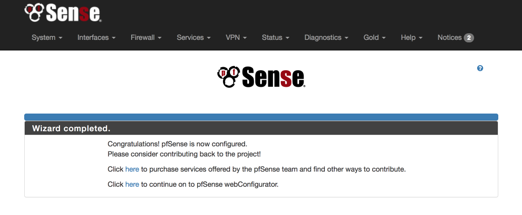
Click the ‘Here’ to enter pfsense webConfigurator and you’ll be presented with the main dashboard where we’ll configure the rest of the system from.
Admin access configuration
We will set up some general configuration options first, using the menu bar at the top of the page.
Navigate to System > Advanced > Admin Access
Web Configurator
To increase security set the GUI access to be via HTTPS and chose a port other than 443, I use 445. One of the reasons for this is to ensure we can generate safe anti-lockout rules which will prevent us locking ourselves out of the GUI when we start creating firewall rules later.
- Protocol: HTTPS
- SSL certificate: webConfigurator default
- TCP Port: 445 (or your preference)
- Max processes: 2
- WebGUI redirect, Disable webConfigurator redirect: [√]
- WebGUI login autocomplete, Enable webConfigurator login: [ ]
- Anti-lockout: [√] Disable webConfigurator anti-lockout rule.
We can disable the system anti-lockour rule as we are going to create our own managed ones during our setup.
Secure Shell
Enable SSH access to pfSense which we will make use of later.
- Enable Secure Shell: [√]
- Authentication Method, Disable password login: [ ]
- SSH port: 22
- Click Save.
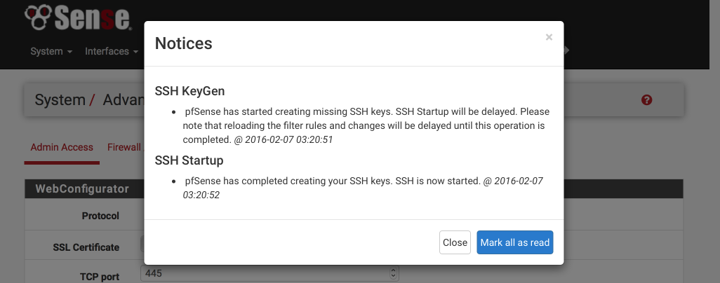
At this point you will be logged out and back in again on the new secure port, i.e https://192.168.1.1:445. When you log back in the banner will have a red warning sign indicating pfSense has started creating SSH keys. Click on the warning and ‘Mark all as read’ to stop the flashing.
Firewall/NAT configuration
Navigate to System > Advanced > Firewall/NAT
Firewall Advanced
- Firewall Optimisation options: conservative. Tries to avoid dropping legitimate idle connections at expense of memory and CPU utilisation.
- Firewall Maximum States: 1633000 (default)
- Firewall maximum table entries: 200000 (default)
Bogon Networks
- Update Frequency: Weekly
- Click Save
Miscellaneous configuration
Navigate to System > Advanced > Miscellaneous
Power Savings
- Use PowerD [√]
- on AC: HiAdaptive
- on Battery: HiAdaptive
- unknown Power: HiAdaptive
Cryptographic Hardware Acceleration
ONLY if you are using an Intel processor select the following. Alternative options are available if you happen to be using an AMD processor.
- Cryptographic Hardware: AES-NI CPU based Acceleration
- Thermal Sensors: Intel Core CPU on-die thermal sensor
- Click Save
Setup VLAN Interfaces
We need to identify a parent interface before we start configuring VLANs, the parent interface refers to the physical interface where the VLANs will reside, e.g igb3 or ix0. You should not assign your parent interface to any interface in pfSense. Its sole function is to act as the parent interface to the VLANs we create.
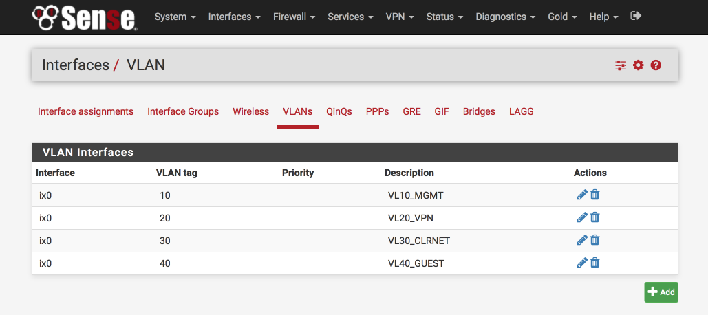
Here’s the VLAN configuration you will end up with at the end of this stage.
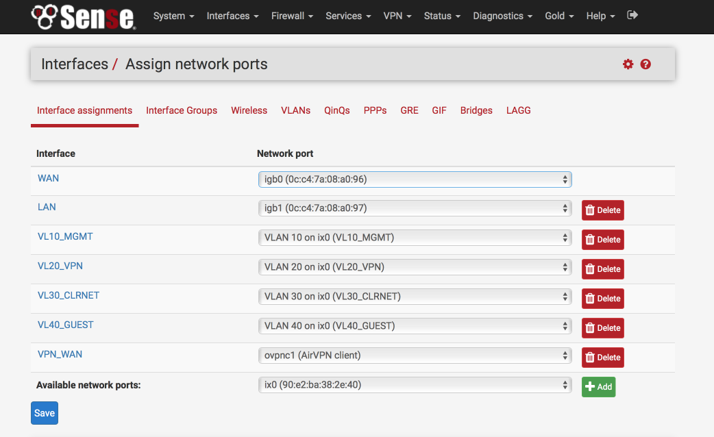
and here’s the interface definitions, note ‘ix0’ at the bottom of the page is unassigned.
Navigate to Interfaces > Assign > VLAN
Create Management VLAN
Click ‘+’
Parent Interface: Your preferred parent interface, in my case, IX0
VLAN Tag: 10
VLAN Priority: 0
Description: VL10_MGMT
Save
Create VPN LAN Interface
Click ‘+”
Parent Interface: Your preferred parent interface, in my case, IX0
VLAN Tag: 20
VLAN Priority: 0
Description: VL20_VPN
Save
Create CLEARNET LAN Interface
Click ‘+”
Parent Interface: Your preferred parent interface, in my case, IX0
VLAN Tag: 30
VLAN Priority: 0
Description: VL30_CLRNET
Save
Create Guest VLAN
Click ‘+”
Parent Interface: Your preferred parent interface, in my case, IX0
VLAN Tag: 40
VLAN Priority: 0
Description: VL40_GUEST
Save
Add VLANs to available Interfaces
Navigate to Interfaces > Assign
Select ‘VLAN10 on IX0’ from the available network ports
Click ‘Add’
Select ‘VLAN20 on IX0’ from the available network ports
Click ‘Add’
Select ‘VLAN30 on IX0’ from the available network ports
Click ‘Add’
Select ‘VLAN40 on IX0’ from the available network ports
Click ‘Add’
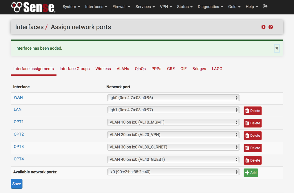
Your interface page should now look something like this.
Set IP address for each VLAN interface
I like to match the third octet of my IP address to the VLAN ID as this makes remembering which is which easier, so VLAN id 10 = 192.168.10.0
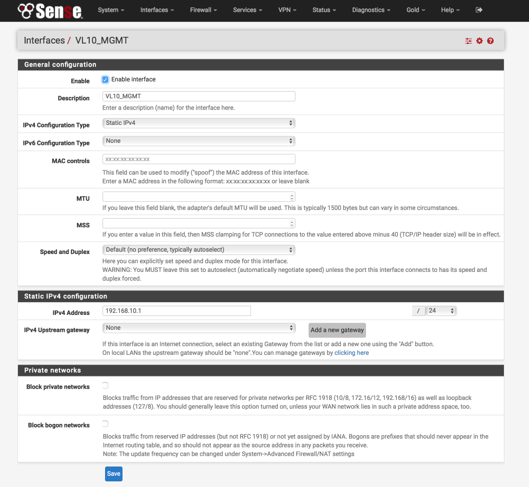
VL10_MGMT Interface
Click on the label next to ‘VLAN10_MGMT’, its likely to be labelled ‘OPT1’
Configure this interface as follows:-
General Configuration
- Enabled = [√]
- Description = VL10_MGMT
- IPv4 = Static IPv4
- IPv6 = None
- Mac address = None
- MTU = None
- MSS = None
- Speed & duplex = standard
Static IPv4 configuration
- IPv4 Address = 192.168.10.1/24
- IPv4 Upstream gateway = None
Private Networks
- Block private networks = [ ]
- Block bogon networks = [ ]
Verify your settings against the image below and Click Save & Apply changes.
VL20_VPN Interface
Navigate back to Interfaces > Assign and configure the VL20_VPN interface by clicking on the label next to the VL20_VPN network port. We’ll configure this exactly the same as the VL10_MGMT Interface except we’ll give it a unique name and IP address.
General Configuration
- Enabled = [√]
- Description = VL20_VPN
Static IPv4 configuration
- IPv4 Address = 192.168.20.1/24
Click Save & Apply changes.
VL30_CLRNET Interface
Navigate back to Interfaces > Assign and configure the VL30_CLRNET interface by clicking on the label next to the VL30_CLRNET network port. We’ll configure this exactly the same as the VL10_MGMT Interface except we’ll give it a unique name and IP address.
General Configuration
- Enabled = [√]
- Description = VL30_CLRNET
Static IPv4 configuration
- IPv4 Address = 192.168.30.1/24
Click Save & Apply changes.
VL40_GUEST Interface
Navigate back to Interfaces > Assign and configure the VL40_GUEST interface by clicking on the label next to the VL40_GUEST network port. We’ll configure this exactly the same as the VL10_MGMT Interface except we’ll give it a unique name and IP address.
General Configuration
- Enabled = [√]
- Description = VL40_GUEST
Static IPv4 configuration
- IPv4 Address = 192.168.40.1/24
Click Save & Apply changes.
Setup DHCP per interface
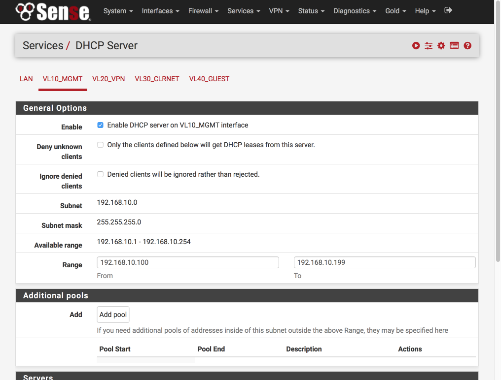
I like to set each interface to use x.x.x.100-199 for dynamic addresses and reserve x.x.x.10-99 for static allocations. Depending on the number of devices in your network you may need to adjust this to suit.
Navigate to Services > DHCP Server
Select VL10_MGMT tab and set the DHCP server as follows:-
- Enabled = [√]
- Range
- From : 192.168.10.100
- To : 192.168.10.199
Verify your settings against the image below (I only display the general options below as the rest are default) and then click Save & Apply
No we’ll set up the rest of the interfaces. Select VL20_VPN tab and set the DHCP server as follows:-
- Enabled = [√]
- Range
- From : 192.168.20.100
- To : 192.168.20.199 - Save & Apply
Select VL30_CLRNET tab and set the DHCP server as below.
- Enabled = [√]
- Range
- From : 192.168.30.100
- To : 192.168.30.199 - Save & Apply
Select VL40_GUEST tab and set the DHCP server as below. I use my Internet providers DNS servers for my guest network. You will need to substitute your ISPs servers instead of mine as you won’t be able to access them unless you are on Verizon too.
- Enabled = [√]
- Range
- From : 192.168.40.100
- To : 192.168.40.199 - DNS Server 1 : 71.252.0.12
- DNS Server 2 : 68.237.161.12
- Save & Apply
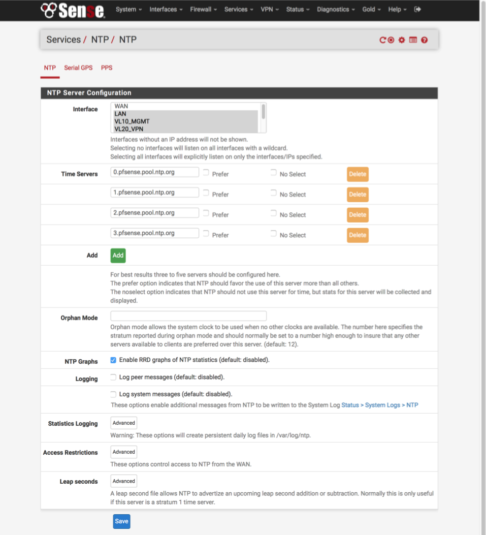
NTP Server
Navigate to Services > NTP
My complete network is synced to my pfSense router with the exception of guest network devices. For best results we will add 4 servers here.
- Interface = LAN, VL10_MGMT, VL20_VPN, VL30_CLRNET
- Time Servers
- 0.pfsense.pool.ntp.org, Prefer [ ], No Select = [ ]
- 1.pfsense.pool.ntp.org, Prefer [ ], No Select = [ ]
- 2.pfsense.pool.ntp.org, Prefer [ ], No Select = [ ]
- 3.pfsense.pool.ntp.org, Prefer [ ], No Select = [ ] - Enable RRD graphs of NTP statistics = [√]
Click Save
Generate AirVPN certificates
Now we’ll generate our required AirVPN certificates. Navigate to airvpn.org and log into your account then navigate to Client Area > Config Generator and enter the following settings.
- Operating System = Router or Other
- Servers = Your preferred Country or Single Server. I prefer to use a single server
- Connection Modes = Advanced [√]
- Direct, protocol UDP, port 443 - Advanced
- Separate keys/certs from .ovpn file [√]
- Resolved hosts in .ovpn file - Terms of Service
- I have read and accept the Terms of Servce [√]
- I HEREBY EXPLICITLY ACCEPT POINTS 8,10,11 [√] - Click on [Generate]
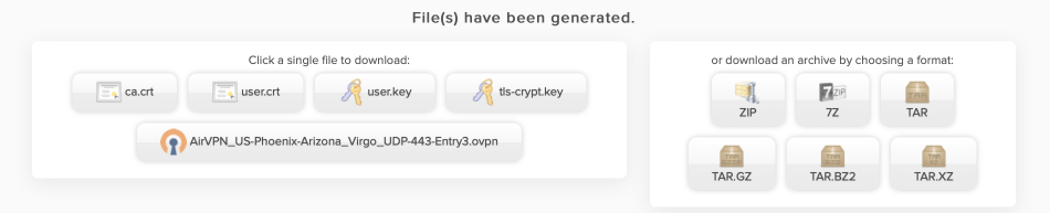
You can now download the certificates to your local machine. Either download one of the packed archives, or download the separate files and extract. We will use these 4 certs and .ovpn config file to configure the OpenVPN client in pfSense in the next step.
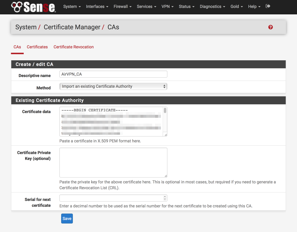
Create AirVPN Certificate Authority
Back in pfSense’s GUI, we’ll create the Certificate Authority first.
Navigate to System > Cert Manager > CAs
- Click ‘+’
- Descriptive Name = AirVPN_CA
- Method = Import an existing Certificate Authority
- Certificate data = Paste contents of ca.crt file in here
- Certificate Private Key (optional) = blank
- Serial for next certificate = blank
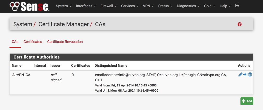
- Click Save
This is what the certificate authority should look like once you’ve added it
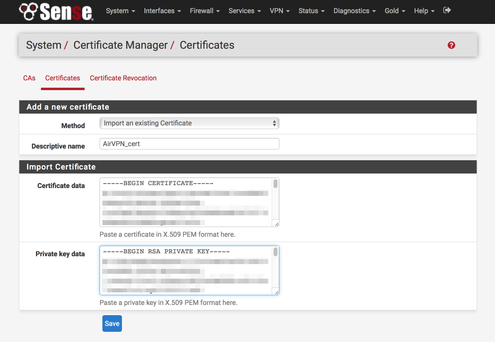
Add AirVPN certificate.
Navigate to System > Cert Manager > Certificates
- Click ‘+’
- Method = Import existing cert
- Descriptive Name = AirVPN_cert
- Certificate data = paste contents of user.crt here
- Private key data = paste contents of user.key here
- Click Save
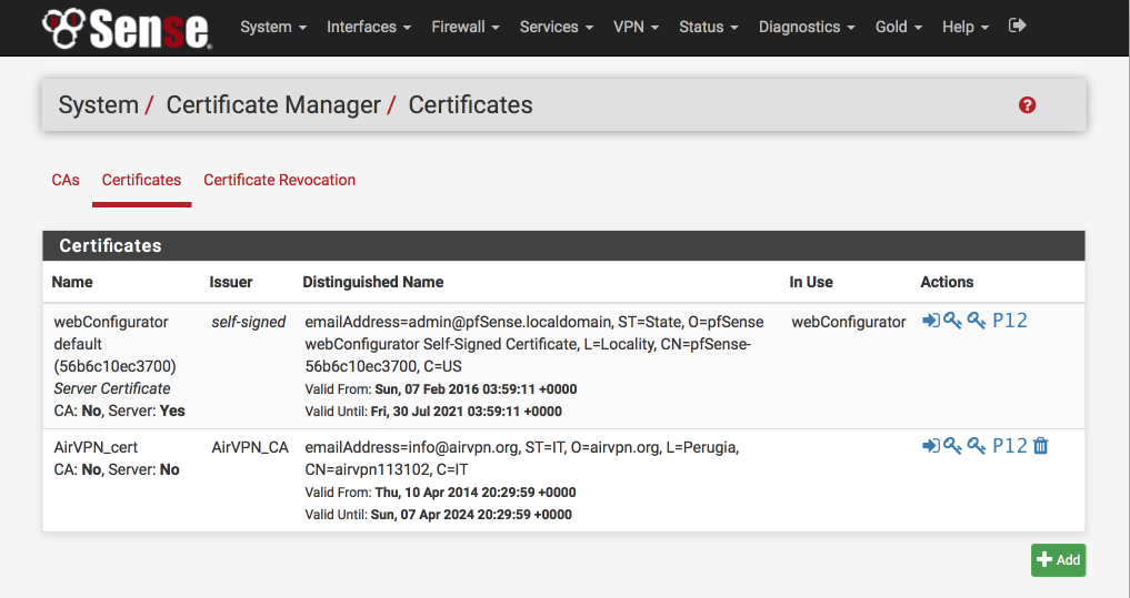
This is what the certificate authority should look like once you’ve added it
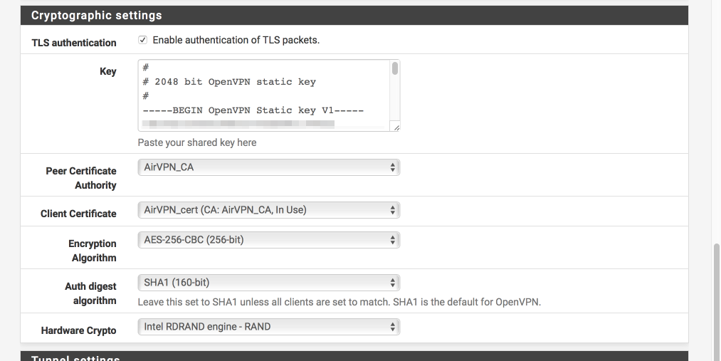
Create VPN connection
We will now configure the VPN connection itself. Most of this page is pretty simple to follow but I’ve included an image to help illustrate the correct key file to use for the Cryptographic settings.
Navigate to VPN > OpenVPN > Client
General Information
- Click ‘+’
- Server Mode = Peer to Peer (SSL / TLS)
- Protocol = UDP
- Device mode = tun
- Interface = WAN
- Local Port = [ ]
- Server host = AirVPN server from the Air VPN configuration file you downloaded. It will look something like
remote 104.243.24.235 443where the first four numbers make up the IP address and the last number is the port number. - Server port = Change this from default OpenVPN port of 1194 to 443 (from Air VPN configuration file)
- Proxy host or address = empty
- Proxy auth - Extra options = empty
- Proxy authentication extra options = none
- Server host name resolution = [√] Infinitely resolve server
- Description = AirVPN client
User Authentication Settings
- Username = [ ]
- Password = [ ]
Cryptographic settings
- Enable authentication of TLS packets = [√]
- Key = Paste contents of the ta.key file you downloaded here
- Peer certificate authority = AirVPN_CA
- Client certificate = AirVPN_cert
- Encryption algorithm = AES-256-CBC
- Auth digest Algorithm = SHA1 (160-bit)
- Hardware crypto = Intel RDRAND (assuming you have an Intel processor)
Tunnel Settings
- Compression: Enabled with Adaptive Compression
- Topology: Subnet - One IP address per clinet in a common subnet
- Dont pull routes [√]
Advanced Configuration
Paste the following into the advanced box
client;remote-cert-tls server;persist-key;persist-tun;keysize 256;key-method 2;key-direction 1;explicit-exit-notify 5;bcast-buffers 4096;fast-io;mlock;keepalive 5 30;prng sha512 64;
- Verbosity = 4 (adjust as needed for debugging / production use etc)
- Click Save
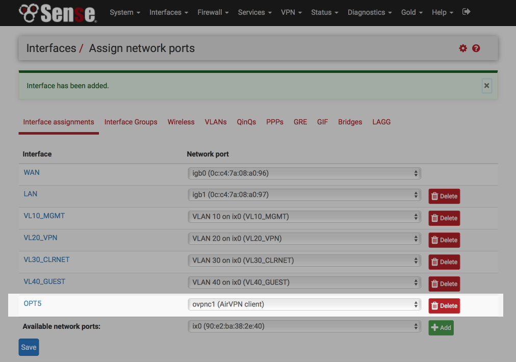
Assign OpenVPN interface
We’ll now assign the OpenVPN interface we just created to a pfSense interface.
Navigate to Interfaces > Assign
- Available network ports: Select ‘ovpnc1 (AirVPN client)`
- Click ‘+’ at the bottom right which will add a new OPTx interface.
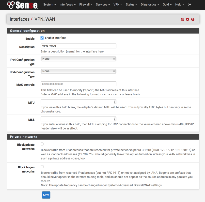
- Click on the new OPTx interface name (OPT5 in my example below).
Set up the interface as follows:
- Enable Interface = [√]
- Description = VPN_WAN
- IPv4 Configuration Type = None
- IPv6 Configuration Type = None
- Mac Address = blank
- MTU = blank
- MSS = blank
- Block private networks = [ ]
- Block bogon networks = [ ]
- Click Save & Apply changes
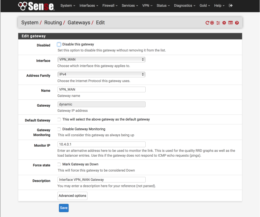
Setup AirVPN Gateway
Its not possible to rename the default created gateway but we can create a new interface based on the system one, call it what we need, and then delete the default gateway.
Navigate to System > Routing.
Its important make sure you click on the ‘+’ alongside the VPN_WAN_VPNV4 line.
The 10.4.0.1 is the AirVPN DNS server for port 443 UDP access. For reference, the other DNS servers are listed here at the bottom of the page.
- Disabled = [ ]
- Interface = VPN_WAN
- Address family = IPv4
- Name = VPN_WAN
- Gateway = dynamic
- Default Gateway = [ ]
- Disable gateway monitoring = [ ]
- Monitor IP = 10.4.0.1
- Forces state = [ ]
- Description = Interface VPN_WAN Gateway
- Click Save
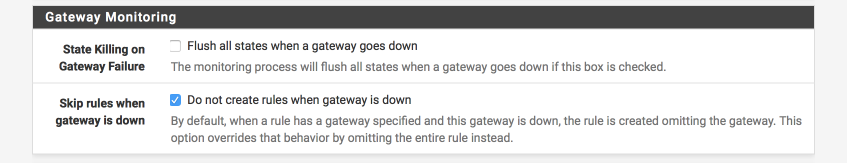
To reduce the chance of any leaks in the event the VPN goes down for any reason.
Navigate to System > Advanced > Miscellaneous
- State Killing on Gateway Failure = [_]
- Skip rules when gateway is down = [√]
- Click Save
Set DNS Resolver
DNS Resolver is a new and significantly updated version of the DNS Forwarder used in pfSense 2.1. There are some complexities and compromises to be aware of currently to facilitate the below feature set whilst providing a leak proof system.
- Support multiple gateways
- Do not leak IP address under any circumstances
- Enable local device lookups
- Support WPAD auto configuration
- Prevent DNS snooping by keeping DNS queries within the VPN tunnel
- Use AirVPNs DNS server to circumvent georestriction of services (iPlayer, Hulu, Netflix etc)
- Improve local performance with result caching
- Support DNS redirection to enable advert/tracker filtering
To support these features, all local devices will be set to use the pfSense router as their sole DNS server. Cached or local names found in the DNS Resolver will be returned to the client and unknown lookups will be forwarded to AirVPN’s global DNS server which in turn resolves results with root name servers. Returned results will be cached for future reference.
To reduce any leaks, I lock down the global lookups to the VPN_WAN interface. The drawback to this is that until the VPN interface is up its not possible to perform and DNS lookups so your AirVPN end point needs to be specified as a IP address rather than name. Also, if the VPN connection goes down, DNS lookups wont be possible and this is why I provide the guest network as a backup in the rare occasions AirVPN has let me down. Its possible to setup multiple simultaneous connections to AirVPN which provides further redundancy and I’ll cover this in another guide. Another compromise is that AirVPN do not provide DNSSEC support on their DNS servers yet.
I believe this is a fair compromise between providing the required functionality and security and I’ve spent time verifying there are no leaks with this setup.
VL40_GUEST is not added to the interfaces selection as devices on that subnet do not utilise the DNS Resolver to resolve name but instead directly accesss the DNS servers as awarded from the DHCP server.
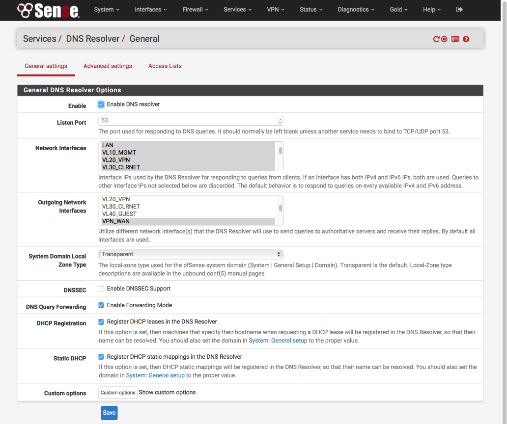
Navigate to Services > DNS Resolver > General Settings
- Enable DNS Resolver = [√]
- Network Interfaces: Select LAN, VL10_MGMT, VL20_VPN, VL30_CLRNET & localhost
- Outgoing Network Interfaces: Select only VPN_WAN
- System Domain Local Zone Type: Transparent
- DNSSEC = [ ]
- DNS Forwarding Mode = [√]
- Register DHCP leases in DNS Forwarder = [√]
- Register DHCP static leases in DNS Forwarder = [√]
- Click Save
Navigate to Services > DNS Resolver > Advanced Settings
- Navigate to Services > DNS Resolver > AdvancedSettings
- Hide Identity = [√]
- Hide Version = [√]
- Prefetch Support = [√]
- Prefetch DNS Key Support = [√]
- Harden DNSSEC Data = [ ]
- Message Cache Size: 4MB
- Outgoing TCP Buffers: 10
- Incoming TCP Buffers = 10
- EDNS Buffer Size: 4096
- Number of queries per thread: 512
- Jostle timeout = 200
- Maximum TTL for RRsets and messages: 86400
- Minimum TTL for RRsets and messages: 0
- TTL for host cache entries: 15 minutes
- Number of hosts to cache: 10000
- Unwanted reply threshold: Disabled
- Log Level: 4 (adjust for debugging or production etc)
- Disable Auto-added Access control = [ ]
- Experimental Bit 0x20 Support = [ ]
- Click Save
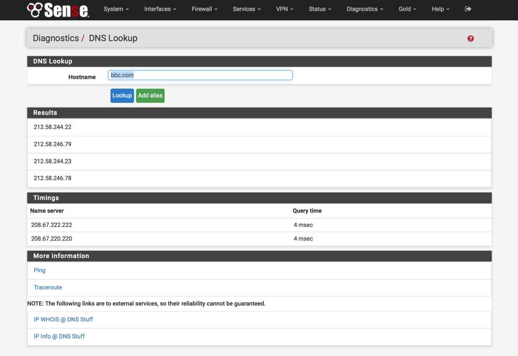
Verify DNS functionality
Its worth verifying that basic DNS lookups work before we complicate matters by introducing the VPN DNS server.
Navigate to Diagnostics > DNS Lookup
- Enter an address to test lookups with, i.e bbc.com.
- Click DNS Lookup
You should see an IP address returned as well as the time taken to receive the response, for example
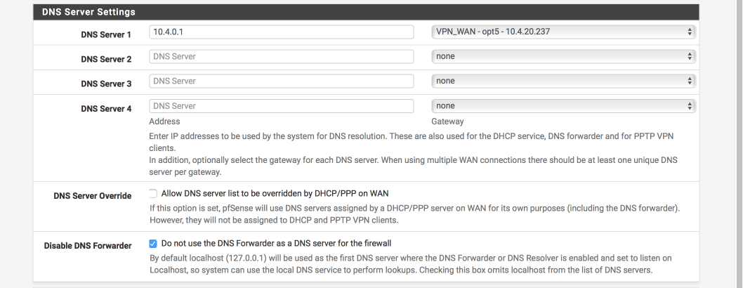
Update DNS server to AirVPN’s
Now you have verified pfSense can perform DNS lookups its a good time to swap the DNS servers over to AirVPNs. This will break DNS functionality until our VPN tunnel is active.
Navigate to System > General Setup
- Delete both OpenDNS servers we used for initial testing
- DNS Server 1: 10.4.0.1, VPN_WAN
- Allow DNS Server list to be overridden by DHCP on WAN: [ ]
- Dont not use the DNS forwarder as the DNS server for the firewall [√]
It should look like this when finished
Set up outgoing NAT for LAN & Localhost
NAT is needed to convert your private local IP addresses to the global registered address space. We’ll set this up for both our WAN and VPN_WAN gateways now.
When you are complete your NAT translation table should look like the image below, specifically
- All subnets can transition to the WAN address range
- VPN subnet can transition to both VPN_WAN & WAN ranges (needed due to a SELECTIVE_ROUTING rule we’ll set up later)
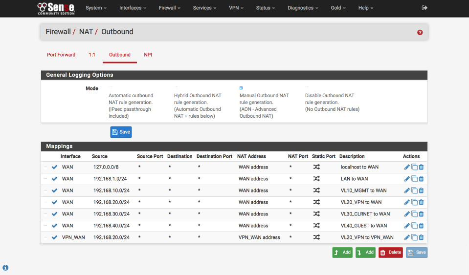
Navigate to Firewall > NAT > Outbound
- Select ‘Manual outbound NAT rule generation`
- Click Save & Apply configuration
A number of rules will be created automatically. Delete any with ‘500’ in the Destination Port column as we won’t need these and it will keep things clear and simple.
Edit ‘localhost to WAN’ NAT
Click the pencil icon next to 127.0.0.0 / 8 line to edit it.
- Disabled = [ ]
- Do not NAT = [ ]
- Interface = WAN
- Protocol = any
- Source
- Type = Network
- Address = 127.0.0.0 / 8
- Source port: Blank - Destination
- Type = Any
- Address = Blank
- Destination Port: Blank - Not : [ ]
- Translation
- Address = Interface Address
- Port = blank - Miscellaneous
- Description = Localhost to WAN - Click Save
Edit ‘LAN to WAN` NAT
Click the pencil icon next to auto created LAN rule line to edit it
- Disabled = [ ]
- Do not NAT = [ ]
- Interface = WAN
- Protocol = any
- Source
- Type = Network
- Source Network = 192.168.1.0 / 24
- Source port: Blank - Destination
- Type = Any
- Address = Blank
- Destination Port: Blank - Not : [ ]
- Translation
- Address = Interface Address
- Port = [ ] - Miscellaneous
- Description = LAN to WAN - Click Save
Edit ‘VL10_MGMT to WAN` NAT
Click the pencil icon next to Auto created VL10_MGMT rule line to edit it
- Disabled = [ ]
- Do not NAT = [ ]
- Interface = WAN
- Protocol = any
- Source
- Type = Network
- Source Network = 192.168.10.0 / 24
- Source port: Blank - Destination
- Type = Any
- Address = Blank
- Destination Port: Blank - Not : [ ]
- Translation
- Address = Interface Address
- Port = [ ] - Miscellaneous
- Description = VL10_MGMT to WAN - Click Save
Edit ‘VL20_VPN to WAN’ NAT
Click the pencil icon next to Auto created VL20_VPN rule line to edit it
- Disabled = [ ]
- Do not NAT = [ ]
- Interface = WAN
- Protocol = any
- Source
- Type = Network
- Source Network = 192.168.20.0 / 24
- Source port: Blank - Destination
- Type = Any
- Address = Blank
- Destination Port: Blank - Not : [ ]
- Translation
- Address = Interface Address
- Port = [ ] - Miscellaneous
- Description = VL20_VPN to WAN - Click Save
Edit ‘VL30_CLRNET to WAN’ NAT
Click the pencil icon next to Auto created VL30_CLRNET rule line to edit it
- Disabled = [ ]
- Do not NAT = [ ]
- Interface = WAN
- Protocol = any
- Source
- Type = Network
- Source Network = 192.168.30.0 / 24
- Source port: Blank - Destination
- Type = Any
- Address = Blank
- Destination Port: Blank - Not : [ ]
- Translation
- Address = Interface Address
- Port = [ ] - Miscellaneous
- Description = VL30_CLRNET to WAN - Click Save
Edit ‘VL40_GUEST to WAN’ NAT
Click the pencil icon next to Auto created VL40_GUEST rule line to edit it
- Disabled = [ ]
- Do not NAT = [ ]
- Interface = WAN
- Protocol = any
- Source
- Type = Network
- Source Network = 192.168.40.0 / 24
- Source port: Blank - Destination
- Type = Any
- Address = Blank
- Destination Port: Blank - Not : [ ]
- Translation
- Address = Interface Address
- Port = [ ] - Miscellaneous
- Description = VL40_GUEST to WAN - Click Save
Setup ‘VL20_VPN to VPN_WAN’ gateway access
Click ‘Add bottom’
- Disabled = [ ]
- Do not NAT = [ ]
- Interface = VPN_WAN
- Protocol = any
- Source
- Type = Network
- Source Network = 192.168.20.0 / 24
- Source port: Blank - Destination
- Type = Any
- Address = Blank
- Destination Port: Blank - Not : [ ]
- Translation
- Address = Interface Address
- Port = [ ] - Miscellaneous
- Description = VL20_VLAN to VPN_WAN - Click Save
Create Aliases for firewall rules
We are going to create a few aliases which we will use in the creation of the firewall rules later. These simplify the job of making changes in future especially as we add more interfaces and functionality to our network.
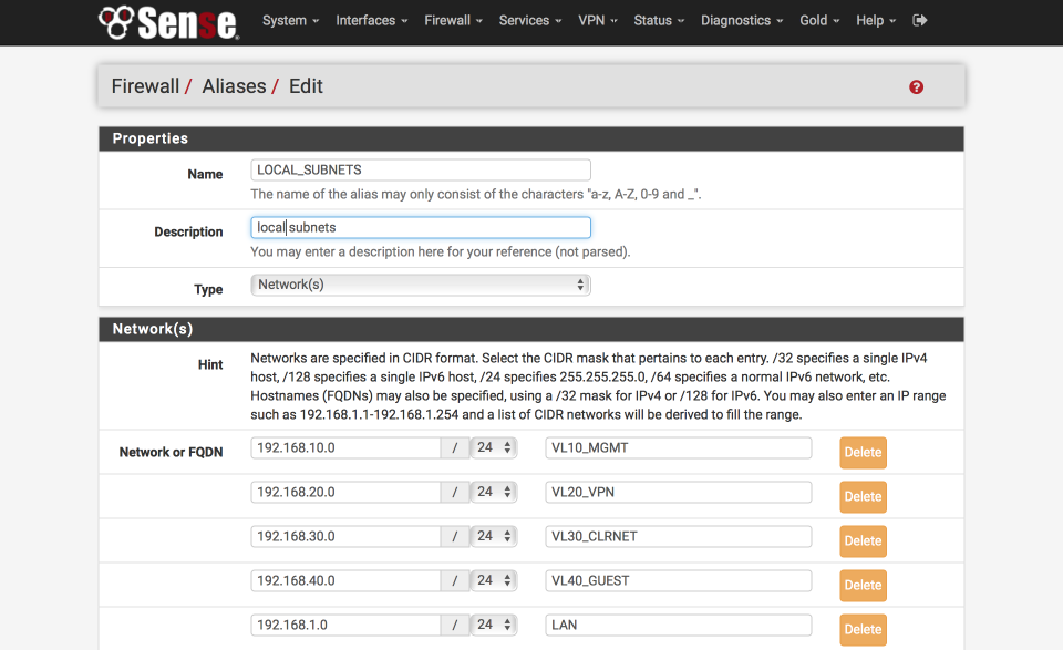
Define local subnets
First we will create an alias to define the internal subnets.
Navigate to Firewall > Aliases > IP
- Click ‘+’
- Name = LOCAL_SUBNETS
- Description = local subnets
- Type = Networks
- 192.168.10.0 / 24 “VL10_MGMT”
- 192.168.20.0 / 24 “VL20_VPN”
- 192.168.30.0 / 24 “VL30_CLRNET”
- 192.168.40.0 / 24 “VL40_GUEST”
- 192.168.1.0 / 24 “LAN”
- Click Save
Define SELECTIVE_ROUTING addresses
We’ll make use of this alias to specify traffic which should leave the VPN subnet via the default system gateway. This creates an empty placeholder list for now.
Navigate to Firewall > Aliases > IP
- Click ‘+’
- Name = SELECTIVE_ROUTING
- Description = IP address to exit VPN via default gateway
- Type = Host(s)
- Click Save
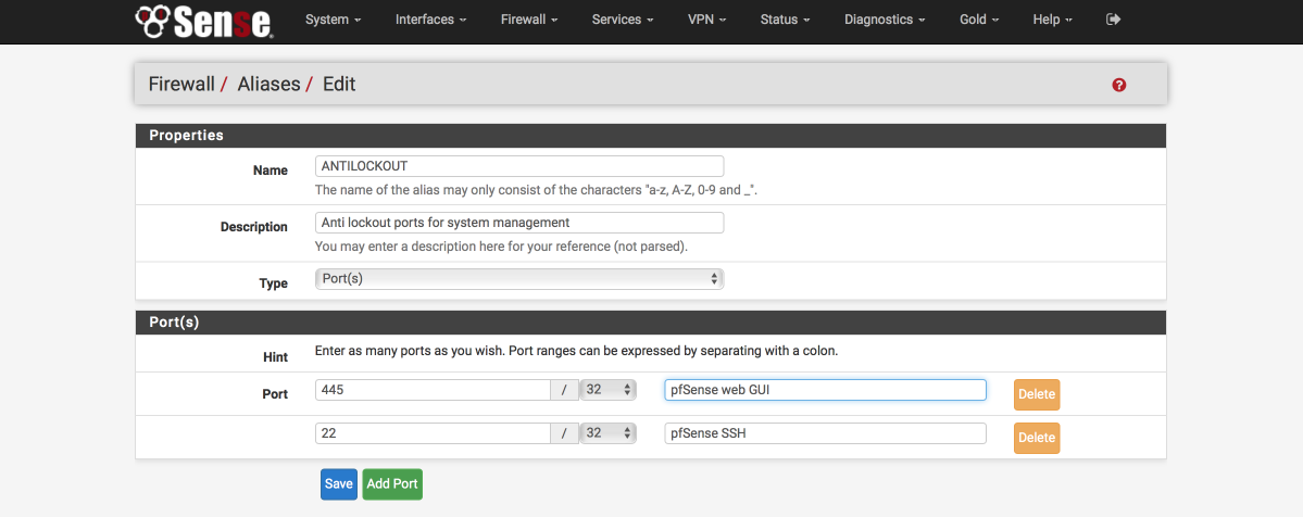
Define anti-lockout ports
We will create a list to define which ports administration traffic flows on, we will allow these ports with a dedicated rule on key interfaces to ensure we don’t lock ourselves out when configuring the firewall. Make sure these ports match the ones you set earlier on the Advanced > Admin Access page for HTTPS and SSH access.
Navigate to Firewall > Aliases > Ports
- Click ‘+’
- Name = ANTILOCKOUT
- Description = Anti-lockout ports for system administration
- Type = Ports
- 445 : pfSense web GUI
- 22 : pfsense SSH
- Click Save
Define ports allowed to communicate between internal subnets
We will create a list of ports to define what traffic is permitted to traverse between our local subnets. You will need to amend this alias as per your own networks requirements but this should get you started. Reviewing the Firewall logs will illustrate which ports are being blocked.
Navigate to Firewall > Aliases > Ports
- Click ‘+’
- Name = Allowed_OUT_ports_LAN
- Description = Open LAN ports
- Type = Ports
- Ports(s) =
- 53 : DNS
- 5353:5354 : MDNS
- 123 : NTP
- 21 : FTP
- 22 : SSH
- 161 : SNMP
- 80 : HTTP
- 443 : HTTPS
- 515 : LPD (Printer)
- 427 : SLP (Printer scanner)
- 631 : IPP (Printer)
- 8080:8081 : Unifi
- 8880 : Unifi redirect HTTP
- 8843 : Unifi redirect HTTPS
- 10001 : UBNT broadcast
- 5001 : iperf
- 5900 : IPMI
- 9000 : VNC
- 3389 : remote desktop
- 49152:65535 : Ephemeral ports - Click Save
Define ports allowed to access the internet
We will create a list of ports to define what is allowed to access the internet. You will need to amend this as per your own networks requirements.
Again, if any programs or services you use stop working, check the firewall logs to see if there are any blocked ports being reported.
Navigate to Firewall > Aliases > Ports
- Click ‘+’
- Name = Allowed_OUT_Ports_WAN
- Description = Open WAN ports
- Type = Ports
- Ports(s) =
- 21 : FTP
- 22 : SSH
- 80 : HTTP
- 443 : HTTPS
- 587 : SMTPS
- 993 : IMAPS
- 5222 : XMPP
- 8080 : HTTP Alt
- 465 : SMTPS
- 119 : NNTP
- 143 : IMAP
- 6667 : IRC
- 6697 : IRCS
- 8443 : CalDAV
- 8843 : CardDAV
- 49152:65535 : ephemeral ports - Click Save
Setup Firewall Rules
Firewall are critical component of securing your network and its worth double checking you have this section set up correctly. Errors here could expose your network to unwanted intruders. I split my IPv4 and IPv6 default blocks out currently but you could combine them into a single rule if you prefer. The order of the rules is important as they are processed from top to bottom. I’ve added images of each interface so you can verify your rules have been created and ordered correctly.
First we will set up the WAN interface. With no rules, all inbound traffic is blocked but isn’t logged. We will add a catch all rule that prevents and more importantly logs inbound traffic so we can be aware of who may be trying to gain access.
WAN rules
Navigate to Firewall > Rules > WAN
- Click ‘↴+’
- Action = Block
- Disabled = [ ]
- Interface = WAN
- Address Family = IPv4
- Protocol = Any
- Source = Any
- Destination = Any
- Log = [√]
- Description = WAN: default block IPv4
-
Click [Save]
- Click ‘↴+’
- Action = Block
- Disabled = [ ]
- Interface = WAN
- Address Family = IPv6
- Protocol = Any
- Source = Any
- Destination = Any
- Log = [ ]
- Description = WAN: default block IPv6
- Click [Save]
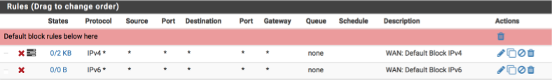
Your WAN interface should look this this when done. (I’ve added some separators to provide notes and aid readability, they aren’t a requirement though so feel free to omit if you prefer)
VPN_WAN rules
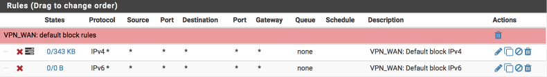
Now we will create similar block rules on the VPN_WAN interface to prevent any unwanted ingress.
Navigate to Firewall > Rules > VPN_WAN and create the following rules:
A rule to block and log IPv4 traffic
- Click ‘↴+’
- Action: Block
- Disabled = [ ]
- Interface: VPN_WAN
- Address Family: IPv4
- Protocol: Any
- Source: Any
- Destination: Any
- Log: [√]
- Description: VPN_WAN: default block IPv4
- Click [Save]
and a rule to block IPv6 traffic
- Click ‘↴+’
- Action: Block
- Disabled = [ ]
- Interface: VPN_WAN
- Address Family: IPv6
- Protocol: Any
- Source: Any
- Destination: Any
- Log: [ ]
- Description: VPN_WAN: default block IPv6
- Click [Save]
Your VPN_WAN interface should look this this when done.
VL10_MGMT rules
My management interface requirements are:
- antilockout to ensure I can always gain access to pfsense.
- allow ICMP pings to facilitate debugging
- allow traffic to my local networks on approved ports
- allow internet traffic on approved ports
- reject any non local NTP time lookups
- reject any other traffic (note: we use reject rather than block on internal interfaces to ensure a response to any programs trying to send traffic preventing delays associated with waiting for time outs to occur)
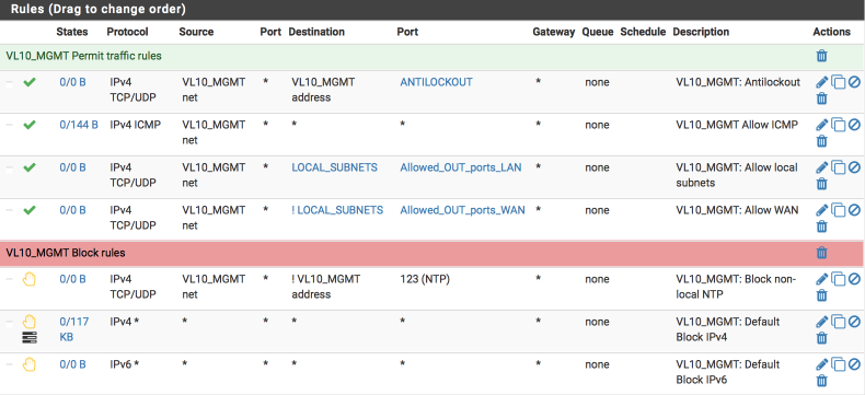
I’ve added some images in to help illustrate the correct way to complete the fields of the rule sheet.
Navigate to Firewall > Rules > VL10_MGMT and create the following rules:
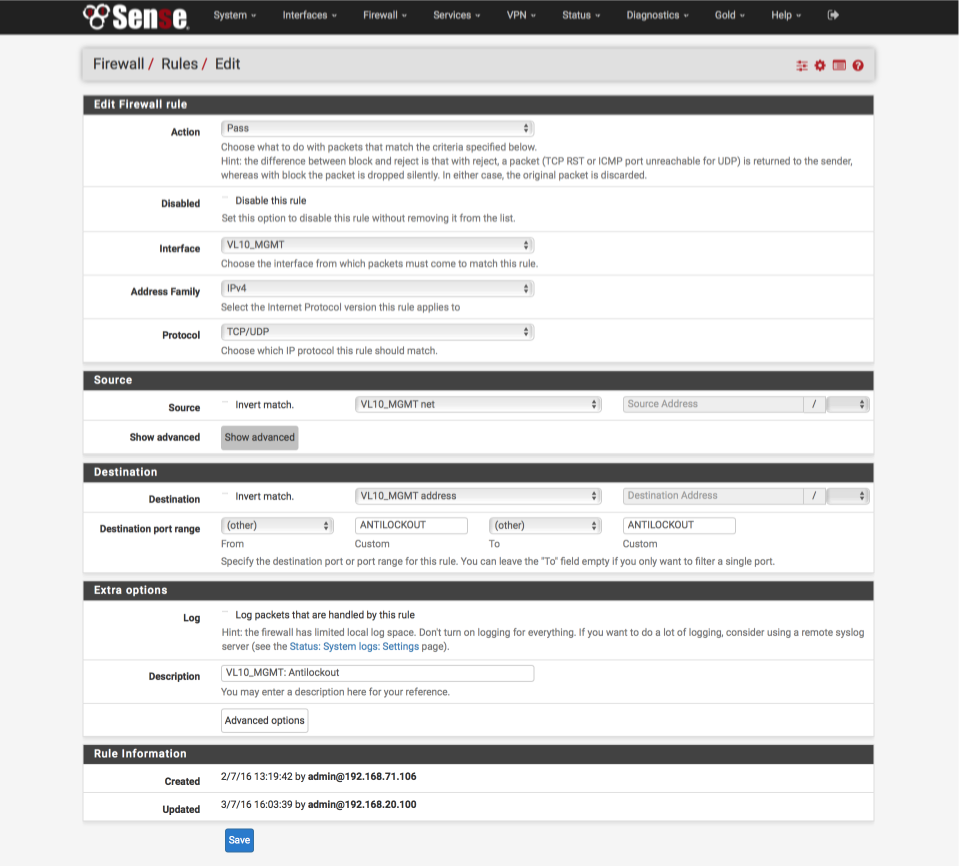
Create the anti-lockout rule ensuring we can always gain access to the GUI and the shell.
- Click ‘↴+’
- Action: Pass
- Disabled: [ ]
- Interface: VL10_MGMT net
- Address Family: IPv4
- Protocol: TCP/UDP
- Source: VL10_MGMT net
- Destination: VL10_MGMT address
- Destination Port range:
- From: Other
- Custom: ANTILOCKOUT
- To: Other
- Custom: ANTILOCKOUT - Log: [ ]
- Description: VL10_MGMT: Antilockout
- Click [Save]
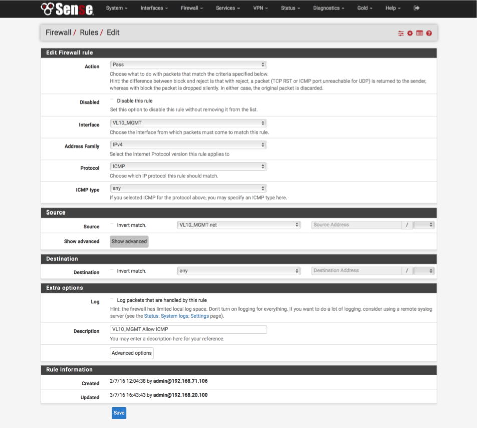
Allow ICMP ‘ping’ debugging from management interface.
- Click ‘↴+’ icon
- Action: Pass
- Disabled: [ ]
- Interface: VL10_MGMT
- Address Family: IPv4
- Protocol: ICMP
- ICMP type: Any
- Source: VL10_MGMT net
- Destination: Any
- Log: [ ]
- Description: VL10_MGMT: Allow ICMP
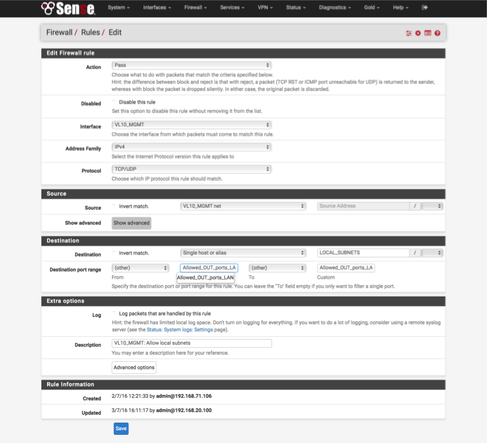
Allow local traffic from management interface to all other subnets.
- Click ‘↴+’ icon
- Action: Pass
- Disabled: [ ]
- Interface: VL10_MGMT
- Address Family: IPv4
- Protocol: TCP/UDP
- Source: VL10_MGMT net
- Destination:
- Invert Match : [ ]
- Single Host or alias: LOCAL_SUBNETS - Destination Port Range:
- From: Other
- Custom: Allowed_OUT_ports_LAN
- To: Other
- Custom: Allowed_OUT_ports_LAN - Log: [ ]
- Description: VL10_MGMT: Allow traffic to local subnets
Allow traffic from management interface to Internet.
We identify traffic destined for the internet as to an interface which is NOT a LOCAL_SUBNETS.
- Click ‘↴+’ icon
- Action: Pass
- Disabled: [ ]
- Interface: VL10_MGMT
- Address Family: IPv4
- Protocol: TCP/UDP
- Source: VL10_MGMT net
- Destination:
- Invert Match : [√]
- Single Host or alias: LOCAL_SUBNETS - Destination Port Range:
- From: Other
- Custom: Allowed_OUT_ports_WAN
- To: Other
- Custom: Allowed_OUT_ports_WAN - Log: [ ]
- Description: VL10_MGMT: Allow traffic to WAN

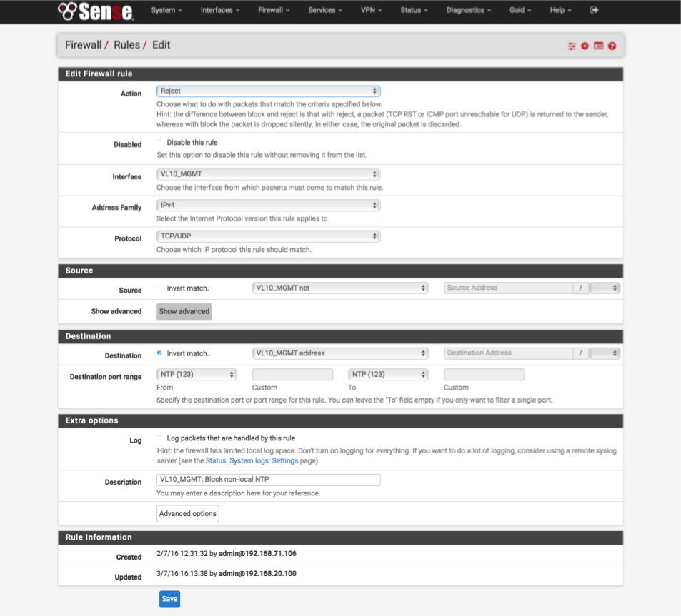
Reject any NTP traffic destined for anywhere except our pfSense box
- Click ‘↴+’ icon
- Action = Reject
- Disabled: [ ]
- Interface = VL10_MGMT
- Address Family: IPv4
- Protocol: TCP/UDP
- Source: VL10_MGMT net
- Destination:
- Invert Match : [x]
- Single Host or alias: VL10__MGMT address - Destination Port Range:
- From: NTP
- To: NTP - Log: [ ]
- Description: VL10_MGMT: Reject non-local NTP
Block unknown IPv4
- Click ‘↴+’ icon
- Action: Reject
- Disabled: [ ]
- Interface: VL10_MGMT
- Address Family: IPv4
- Protocol: Any
- Source = Any
- Destination: Any
- Log = [√]
- Description: VL10_MGMT: default block IPv4
- Click [Save]
Block unknown IPv6
- Click ‘↴+’ icon
- Action: Reject
- Disabled: [ ]
- Interface: VL10_MGMT
- Address Family: IPv6
- Protocol: Any
- Source: Any
- Destination: Any
- Log: [ ]
- Description: VL10_MGMT: default block IPv6
- Click [Save]
Your VL10_MGMT interface should look this this when done.
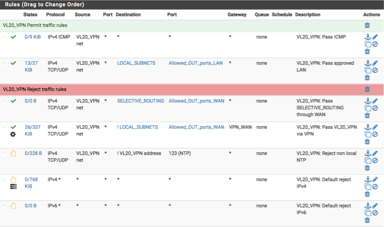
VL20_VPN rules
Now we will create the rules for our VPN and primary local interface, the requirements for this interface are:
- allow ICMP pings to facilitate debugging
- allow traffic to my local networks on approved ports
- allow select internet traffic on approved ports via default WAN gateway
- allow internet traffic on approved ports via VPN gateway
- reject any non local NTP time lookups
- reject any other traffic
Navigate to Firewall > Rules > VL20_VPN and create the following rules.
Allow Pings for network diagnostics
- Click ‘↴+’ icon
- Action: Pass
- Disabled = [ ]
- Interface: VL20_VPN
- Address Family: IPv4
- Protocol: ICMP
- ICMP type: Any
- Source: VL20_VPN net
- Destination: Any
- Log: [ ]
- Description: VL20_VPN: Allow ICMP
Allow traffic to local subnets (LOCAL_SUBNETS alias) on permitted ports only (Allowed_OUT_ports_LAN alias).
- Click ‘↴+’
- Action: Pass
- Disabled = [ ]
- Interface: VL20_VPN
- Address Family: IPv4
- Protocol: TCP/UDP
- Source: VL20_VPN net
- Destination:
- invert match: [ ]
- Single host or alias:
- LOCAL_SUBNETS - Destination Port Range:
- From: Other
- Custom: Allowed_OUT_ports_LAN
- To: Other
- Custom: Allowed_OUT_ports_LAN - Log: [ ]
- Description: VL20_VPN: Pass approved LAN
- Click [Save]
Allow specified traffic to route out over the default unencrypted gateway. This is useful for sites which block VPNs or require you to expose your true location, for example, banking sites.
- Click ‘↴+’
- Action: Pass
- Disabled = [ ]
- Interface: VL20_VPN
- Address Family: IPv4
- Protocol: TCP/UDP
- Source: VL20_VPN net
- Destination: Single Host or alias
- Address: SELECTIVE_ROUTING - Destination Port Range:
- From: Other
- Custom: Allowed_OUT_ports_WAN
- To: Other
- Custom: Allowed_OUT_ports_WAN - Log: [ ]
- Description: VL20_VPN: Pass SELECTIVE_ROUTING sites through default WAN
- Click [Save]
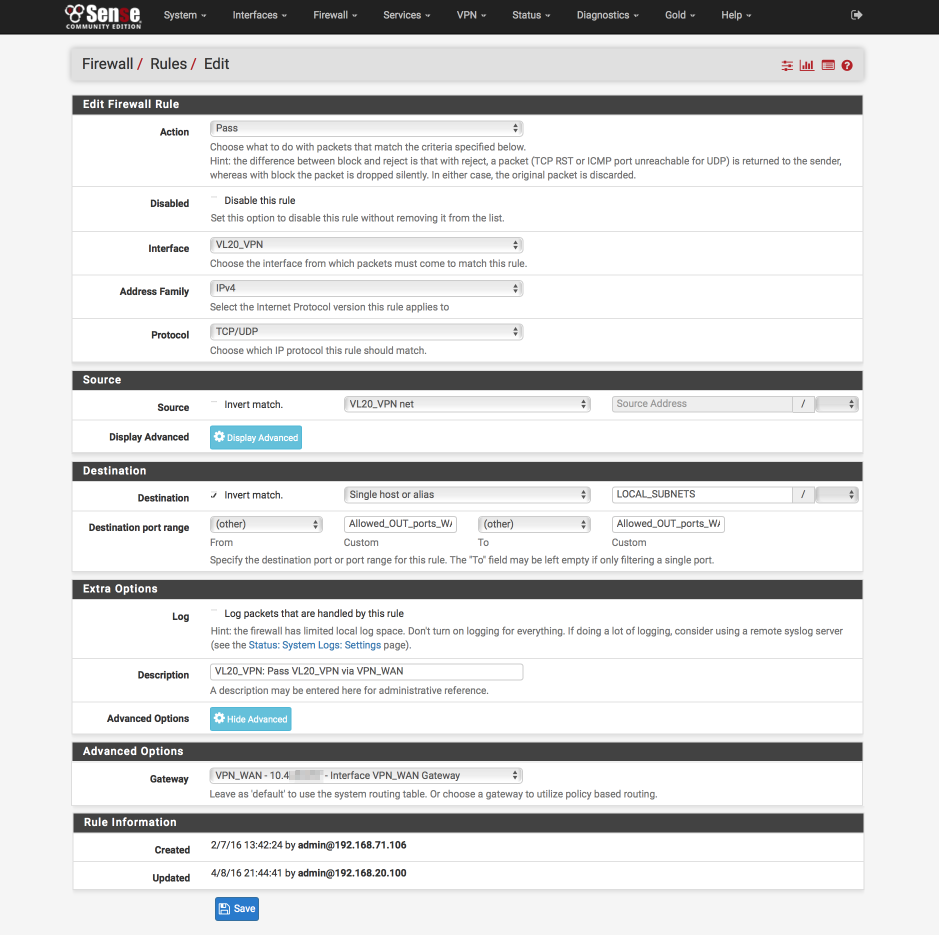
Pass approved internet bound traffic out the VPN gateway
- Click ‘↴+’
- Action: Pass
- Disabled = [ ]
- Interface: VL20_VPN
- Address Family: IPv4
- Protocol: TCP/UDP
- Source: VL20_VPN net
- Destination:
- Invert Match: [√]
- Single host or alias
- Address: LOCAL_SUBNETS - Destination Port Range:
- Invert match: [ ]
- From: Other
- Custom: Allowed_OUT_ports_WAN
- To: Other
- Custom: Allowed_OUT_ports_WAN - Log = [ ]
- Description: VL20_VPN: Pass VPN_WAN
- Click Advanced Options
- Gateway: VPN_WAN
- Click [Save]
Block non local NTP lookups
- Click ‘↴+’
- Action: Reject
- Disabled = [ ]
- Interface: VL20_VPN
- Address Family: IPv4
- Protocol: TCP/UDP
- Source: VL20_VPN net
- Destination:
- Invert Match: [√]
- Address: VL20_VPN address - Destination Port Range:
- From: NTP
- To: NTP - Log: [ ]
- Description: VL20_VPN: Reject non local NTP
- Click [Save]
Default Block & log IPv4
- Click ‘↴+’
- Action: Reject
- Disabled = [ ]
- Interface: VL20_VPN
- Address Family: IPv4
- Protocol: Any
- Source: Any
- Destination: Any
- Log: [√]
- Description: VL20_VPN: Default reject IPv4
- Click [Save]
Block default IPv6
- Click ‘↴+’
- Action: Reject
- Disabled = [ ]
- Interface: VL20_VPN
- Address Family: IPv6
- Protocol: Any
- Source: Any
- Destination: Any
- Log: [ ]
- Description: VL20_VPN: Default reject IPv6
- Click [Save]
Your VL20_VPN interface should look this this when done.
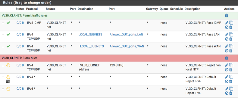
VL30_CLRNET rules
Now we will create the rules for our unencrypted ‘clearnet’ local interface, the requirements for this interface are:
- allow ICMP pings to facilitate debugging
- allow traffic to my local networks on approved ports
- allow internet traffic on approved ports via default gateway
- reject any non local NTP time lookups
- reject any other traffic
Navigate to Firewall > Rules > VL30_CLRNET and create the following rules:-
Allow Pings for network diagnostics
- Click ‘↴+’
- Action: Pass
- Disabled = [ ]
- Interface: VL30_CLRNET
- Address Family: IPv4
- Protocol: ICMP
- ICMP Type: Any
- Source: VL30_CLRNET net
- Destination: Any
- Log: [ ]
- Description: VL30_CLRNET: Pass ICMP
- Click [Save]
Allow traffic to local subnets (LOCAL_SUBNETS alias) on permitted ports only (Allowed_OUT_ports_LAN alias).
- Click ‘↴+’
- Action: Pass
- Disabled = [ ]
- Interface: VL30_CLRNET
- Address Family: IPv4
- Protocol: TCP/UDP
- Source: VL30_CLRNET net
- Destination:
- invert match: [ ]
- Single host or alias
- LOCAL_SUBNETS - Destination Port Range:
- From: Other
- Custom: Allowed_OUT_ports_LAN
- To: Other
- Custom: Allowed_OUT_ports_LAN - Log: [ ]
- Description: VL30_CLRNET: Pass approved LAN
- Click [Save]
Pass approved internet bound traffic out the default system gateway, i.e not the VPN connection
- Click ‘↴+’
- Action: Pass
- Disabled = [ ]
- Interface: VL30_CLRNET
- Address Family: IPv4
- Protocol: TCP/UDP
- Source: VL30_CLRNET net
- Destination:
- Invert Match: [√]
- Single host or alias
- LOCAL_SUBNETS - Destination Port Range:
- From: Other
- Custom: Allowed_OUT_ports_WAN
- To: Other
- Custom: Allowed_OUT_ports_WAN - Log: [ ]
- Description:VL30_CLRNET: Pass WAN
- Click [Save]
Block rogue NTP lookups
- Click ‘↴+’
- Action: Reject
- Disabled = [ ]
- Interface: VL30_CLRNET
- Address Family: IPv4
- Protocol: TCP/UDP
- Source: VL30_CLRNET net
- Destination:
- Invert Match: [√]
- Source: VL30_CLRNET address - Destination Port Range:
- From: NTP
- To: NTP - Log: [ ]
- Description: VL30_CLRNET: Reject non local NTP
- Click [Save]
Default block & log IPv4
- Click ‘↴+’
- Action: Reject
- Disabled = [ ]
- Interface: VL30_CLRNET
- Address Family: IPv4
- Protocol: Any
- Source: Any
- Destination:Any
- Log: [√]
- Description: VL30_CLRNET: Default reject IPv4
- Click [Save]
Default block IPv6
- Click ‘↴+’
- Action: Reject
- Disabled = [ ]
- Interface: VL30_CLRNET
- Address Family: IPv6
- Protocol: Any
- Source: Any
- Destination Any
- Log: [ ]
- Description: VL30_CLRNET: Default reject IPv6
- Click [Save]
Your VL30_CLRNET interface should look this this when done.
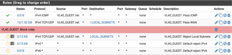
VL40_GUEST
Our GUEST network is a special case. Critically, we do not allow guests access to access any internal devices or subnets. The requirements for the guest interface are:
- allow ICMP pings to facilitate debugging
- deny traffic to any local networks
- allow internet traffic via default gateway
- allow non-local NTP time lookups
- allow non-local DNS lookups (DHCP allocates ISP’s DNS Servers)
- reject any other traffic
Navigate to Firewall > Rules > VL40_GUEST and create the following rules:-
Allow Pings for network diagnostics.
- Click ‘↴+’
- Action = Pass
- Disabled = [ ]
- Interface = VL40_GUEST
- Address Family = IPv4
- Protocol = ICMP
- ICMP Type = Any
- Source = VL40_GUEST net
- Destination = Any
- Log = [ ]
- Description = VL40_GUEST: Pass ICMP
- Click [Save]
Allow guests to access the internet uncensored (this also permits DNS/port 53 and NTP/port 123 traffic).
- Click ‘↴+’
- Action = Pass
- Disabled = [ ]
- Interface = VL40_GUEST
- Address Family = IPv4
- Protocol = TCP/UDP
- Source = VL40_GUEST net
- Destination
- invert match: [√]
- Single host or alias
- Address: LOCAL_SUBNETS - Destination Port Range:
- From: Any
- To: Any - Log = [ ]
- Description = VL40_GUEST: Pass WAN
- Click [Save]
Block any attempts to access local devices or subnets. I also log any matches of this rule so I can see if any guests are attempting to access my local networks.
- Click ‘↴+’
- Action = Reject
- Disabled = [ ]
- Interface = VL40_GUEST
- Address Family = IPv4
- Protocol = TCP/UDP
- Source = VL40_GUEST net
- Destination
- invert match: [ ]
- Single host or alias
- Address: LOCAL_SUBNETS - Destination Port Range:
- From: Any
- To: Any - Log = [√]
- Description = VL40_GUEST: Reject any local traffic
- Click [Save]
Default block & log IPv4
- Click ‘↴+’
- Action = Reject
- Disabled = [ ]
- Interface = VL40_GUEST
- Address Family = IPv4
- Protocol = Any
- Source = Any
- Destination:Any
- Log = [√]
- Description = VL40_GUEST: Default reject IPv4
- Click [Save]
Default block IPv6
- Click ‘↴+’
- Action = Reject
- Disabled = [ ]
- Interface = VL40_GUEST
- Address Family = IPv6
- Protocol = any
- Source = Any
- Destination: Any
- Log = [ ]
- Description = VL40_GUEST: Default reject IPv6
- Click [Save]
Your VL40_GUEST interface should look this this when done.
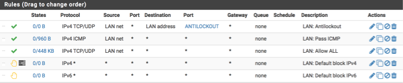
LAN
My LAN interface is treated rather differently. Its mainly used for debugging and as such it can be reconfigured from time to time. As a initial setup I usually configure it with the following requirements in mind.
- provide anti-lockout for last ditch resource to gain access if I really mess something up
- allow ICMP pings to facilitate debugging
- allow any traffic to local subnets
- allow any traffic to internet via default gateway, not VPN
- reject any other traffic
Navigate to Firewall > Rules > LAN and create the following rules:-
Allow Pings for network diagnostics
Create the anti-lockout rule ensuring we can always gain access to the GUI and the shell.
- Click ‘↴+’
- Action: Pass
- Disabled = [ ]
- Interface: LAN net
- Address Family: IPv4
- Protocol: TCP/UDP
- Source: LAN net
- Destination: LAN address
- Destination Port range:
- From: Other
- Custom: ANTILOCKOUT
- To: Other
- Custom: ANTILOCKOUT - Log: [ ]
- Description: LAN: Antilockout
- Click [Save]
Create the rule to allow ICMP pings
- Click ‘↴+’
- Action: Pass
- Disabled = [ ]
- Interface: LAN
- Address Family: IPv4
- Protocol: ICMP
- Source: LAN net
- Destination: Any
- Log: [ ]
- Description: LAN: Pass ICMP
- Click [Save]
Pass all traffic, local or internet bound
- Click ‘↴+’
- Action: Pass
- Disabled = [ ]
- Interface: LAN
- Address Family: IPv4
- Protocol: TCP/UDP
- Source: LAN net
- Destination: Any
- Destination Port range:
- From: Any
- To: Any - Log: [ ]
- Description: LAN: Pass All
- Click [Save]
Default block & log IPv4
- Click ‘↴+’
- Action: Reject
- Disabled = [ ]
- Interface: LAN
- Address Family: IPv4
- Protocol: Any
- Source: Any
- Destination: Any
- Log: [√]
- Description: LAN: Default reject IPv4
- Click [Save]
Default block IPv6
- Click ‘↴+’
- Action: Reject
- Disabled = [ ]
- Interface: LAN
- Address Family: IPv6
- Protocol: Any
- Source: Any
- Destination: Any
- Log: [ ]
- Description: LAN: Default reject IPv6
- Click [Save]
Your LAN interface should look this this when done.
Reboot
This would be a good time to restart your firewall box. The system should boot and allow you to log back into the dashboard where if everything is correct, the WAN and VPN_WAN interfaces will have IP addresses allocated to them.
If things don’t work as expected, make use of the system logs by navigating to Status > System Logs. The various tabs there will allow you to investigate all areas of the firewall and most likely help you track down any issues.
Verification of functionality and performance
Connect up your managed switch and assuming you have correctly configured the trunk port and tagged LAN ports you should be able to go ahead and test the various subnets work correctly. I plan on putting a guide together around configuring a cheap managed switch to go along with this guide just havent got round to it yet.
Verify you are allocated a valid IP address on each subnet,
Here I am connected to the VL20_VPN network and awarded a 192.168.20.100 address.
$ ifconfig en0
en0: flags=8963<UP,BROADCAST,SMART,RUNNING,PROMISC,SIMPLEX,MULTICAST> mtu 1500
    ether b8:e8:56:30:90:5e
    inet6 fe80::bae8:56ff:fe30:905e%en0 prefixlen 64 scopeid 0x4
    inet 192.168.20.100 netmask 0xffffff00 broadcast 192.168.20.255
    nd6 options=1<PERFORMNUD>
    media: autoselect
    status: active
Verify DNS lookups work correctly.
Note the DNS server is the gateway device except on the guest network which we verify below.
$ nslookup pfsense.org
Server:     192.168.20.1
Address:    192.168.20.1#53

Non-authoritative answer:
Name:   pfsense.org
Address: 208.123.73.69
Verify DNS lookups to non local devices are blocked.
Here I use the dig command and force a DNS query to use Googles DNS server (8.8.8.8). This should and does fail.
$ dig @8.8.8.8 pfsense.org

; <<>> DiG 9.8.3-P1 <<>> @8.8.8.8 pfsense.org
; (1 server found)
;; global options: +cmd
;; connection timed out; no servers could be reached
Verify local name resolution is working correctly.
I use nslookup to lookup my pfsense gateway by its hostname and observer the address is returned correctly.
$ nslookup pfsense
Server:     192.168.20.1
Address:    192.168.20.1#53

Name:   pfsense.local.lan
Address: 192.168.1.1
Verify VL40_GUEST functionality
Verify VL40_GUEST DNS lookups.
Note the server here should not be your gateway but your ISP’s DNS servers.
$ nslookup pfsense.org
Server:     71.252.0.12
Address:    71.252.0.12#53

Non-authoritative answer:
Name:   pfsense.org
Address: 208.123.73.69
VL40_GUEST network can not access local devices.
Attempt to access another of your local networked devices and you should be blocked.
Verify VPN connection
Open a browser and head over to AirVPN.org.
For the VPN subnet you should see a valid connection to a AirVPN server in the header bar.

For the GUEST subnet you will observe your own IP address instead.

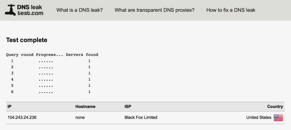
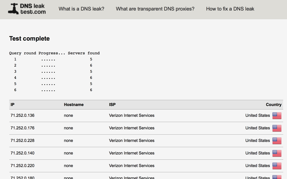
Verify there are no DNS leaks
Open a browser and head over to DNSLeaktest.com.
It worth running an extended test on each subnet to verify functionality.
My VPN subnet isn’t leaking identifying only a single DNS server.
My Guest network as expected shows up multiple Verizon servers.
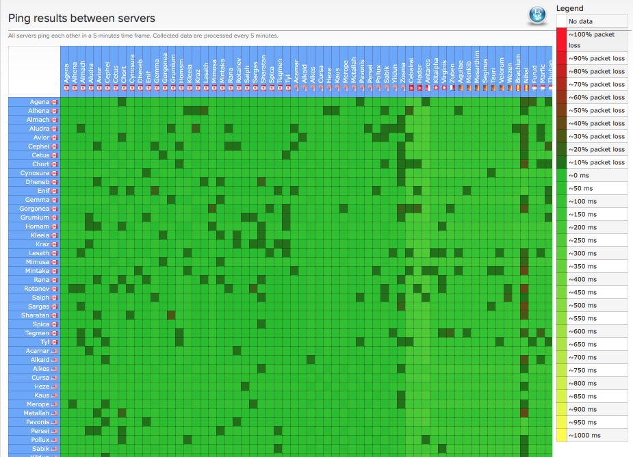
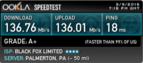
Performance
Performance can fluctuate depending on server loads especially during certain peak times. Make sure to select a server which is close to your geographical location and also one that isn’t heavily utilised. AirVPN’s ping matrix is a useful tool to help identify suitable servers. At best I would expect a 15ms increase in ping times and a reduction in throughput of around 10%, this seems to have held as my line performance has increased.
I validated performance with speedtest.net.
Here’s my LAN performance illustrating Verizon’s FIOS 150/150 service performance.
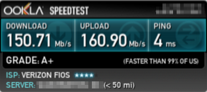
and here’s my VL20_VPN performance
Changelog
7 March 2016
Added changelog
Added clarification around VL40_GUEST & DNS Resolver.
Correct and tidied multiple firewall rules.
Added additional images to aid understandability for new users.
Added disable systems default antilockout rule in favour of our own.
9 March 2016
Added clarity around testing and performance expectations.
30 March 2016
Fixed error in Setup ‘VL20_VPN to VPN_WAN’ NAT rule
5 April 2016
Moved NTP section later in guide to ensure VLAN interfaces are created
Updated antilockout rule to match SSH port 22 (previously 422)
Corrected typo in VLAN Guest interface correction
Added LAN NAT rule
Fixed type in VL30_CLRNET ICMP firewall rule
9 April 2016
Updated VL20 firewall rule images
22 May 2016
Added link to Netgear GS108E configuration guide